This page gives information on the numerous interfaces of the Atari ST and the associated connectors and cables. It also provides information on some standard cables and connectors not specific but useful for the Atari ST.
Important note: On this page the connectors pinout are always given looking at them from the front side and not from the solder side.
LOCATION OF THE INTERFACES CONNECTORS
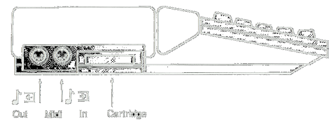
On the left side you find connectors for the midi in and out, and a cartridge
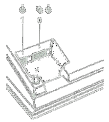
On the right underside contains the connectors for the Mouse & Joysticks
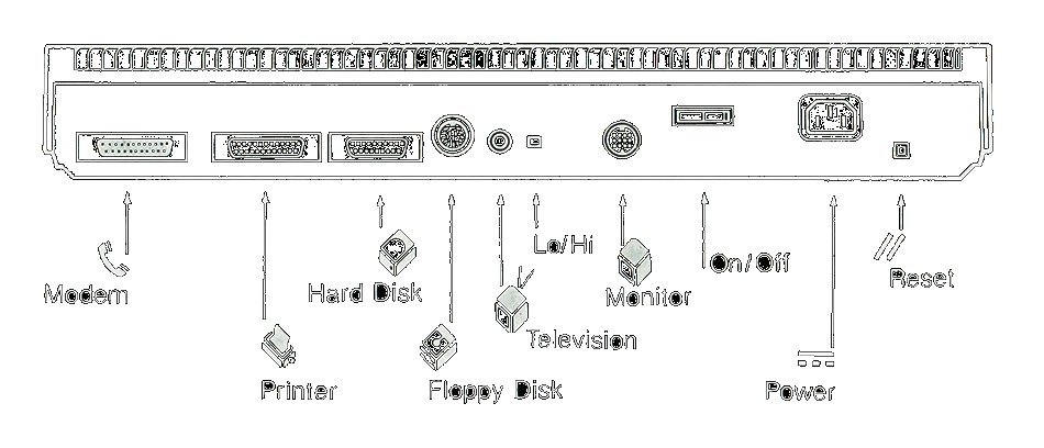
On the back panel you find connectors for a modem, printer,
hard disks, floppy disk,
TV (Atari with RF modulator) and monitor
 Back to the top
ATARI MIDI INTERFACE
 Atari Midi Connectors
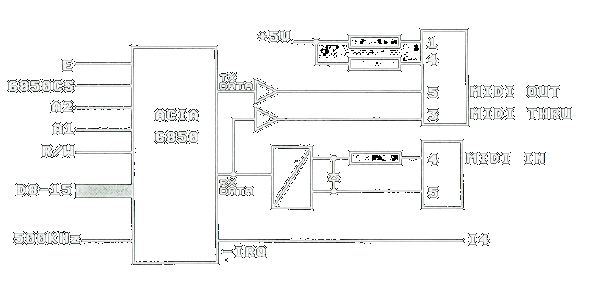
The midi interface is used to connect the Atari to electronic musical instruments. It uses asynchronous signals (8 bits plus start and stop bits) at 31250 bauds (bit/sec). The Atari interfaces midi through a dedicated 6850 ACIA (Asynchronous Communication Interface Adapter) chip as shown on the right.
Note the unconventional connection of Midi Thru signals to pin 1 & 3 of the out midi connector. This allows to have a midi thru interface without the cost of an extra connector.
Back to the topAtari Midi Connectors
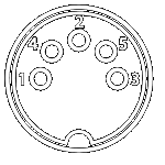
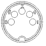
The Atari has two midi DIN5 connectors: A standard Midi In connector, and a non standard Midi Out connector that also includes the Midi thru output (this was done to avoid adding a third connector as specified in the standard midi)
|
 |
||||||||||
| Midi Out/Thru Pinout | DIN5 female | ||||||||||
|
|
||||||||||
| Midi In Pinout | DIN5 female |
Note that a shield is connected on the Midi Out connector which is not following the midi standard. It is therefore recommanded to use cable without shield connection. For the Midi In connector there is no shield which is standard midi.
Back to the topStandard Midi Cables
It is possible to use standard Midi cables for the Midi In and the Midi Out connection to/from the Atari. However it is mandatory to check that the cable connected to the Atari Midi Out does not have any wires connected to pin 1 & 3. This should be the case if you use a "standard midi cable" as describe below, but sometimes you will find DIN5 male-male audio cables that connects all the pins.
|
|
|||||
| Name | DIN5 | DIN5 | ||||
| Shield | 2 | 2 | ||||
| Data | 4 | 4 | ||||
| Loop return | 5 | 5 |
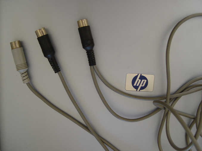
Atari Special Midi Out Midi Thru Cable
It is possible to build a special Y cable that allows to have a Midi Out port as well as a Midi Thru port coming from the Atari. For that matter you need to connect two cables on a male DIN5 connector (the one connected to the Atari Midi Out) and each of them are terminate on a male DIN5 connector. The Y cable connections are described below. Here is a picture of this cable
|
|
|
|||||||
| Name | Atari Out DIN5 | Midi Thru DIN5 | Midi Out DIN5 | ||||||
| Thru sink | 1 | 4 | |||||||
| Shield | 2 | 2 | 2 | ||||||
| Thru source | 3 | 5 | |||||||
| out sink | 4 | 4 | |||||||
| out source | 5 | 5 |
ATARI CARTRIDGE INTERFACE
This interface allows to use a ROM cartridge with a maximum size of 128KB. It connects the internal bus with the cartridge connector as described below.
Pin |
Name | Pin |
Name | |||
| 1 | + 5 VDC | 21 | Address 8 | |||
| 2 | + 5 VDC | 22 | Address 14 | |||
| 3 | Data 14 | 23 | Address 7 | |||
| 4 | Data 15 | 24 | Address 9 | |||
| 5 | Data 12 | 25 | Address 6 | |||
| 6 | Data 13 | 26 | Address 10 | |||
| 7 | Data 10 | 27 | Address 5 | |||
| 8 | Data 11 | 28 | Address 12 | |||
| 9 | Data 8 | 29 | Address 11 | |||
| 10 | Data 9 | 30 | Address 4 | |||
| 11 | Data 6 | 31 | ROM Select 3 | |||
| 12 | Data 7 | 32 | Address 3 | |||
| 13 | Data 4 | 33 | ROM Select 4 | |||
| 14 | Data 5 | 34 | Address 2 | |||
| 15 | Data 2 | 35 | Upper Data Strobe | |||
| 16 | Data 3 | 36 | Address 1 | |||
| 17 | Data 0 | 37 | Lower Data Strobe | |||
| 18 | Data 1 | 38 | Ground | |||
| 19 | Address 13 | 39 | Ground | |||
| 20 | Address 15 | 40 | Ground |
ATARI SERIAL INTERFACE
 Serial Interface Connector
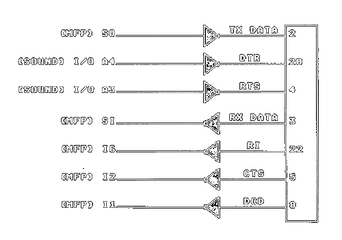
This interface is used generally for communication with other computers or
with modems. Most of the connection comes from the USART (Universal
Synchronous/Asynchronous Receiver/Transmitter) inside the MFP68901 with
the exception of the
DTR and RTS signals that comes from the I/O port of the
sound chip.
The modem interface on Atari ST computers follows the RS232
standard apart from the following non-tested information: The CTS signal (that usually indicates that the modem is ready to take the next
character) is connected to input I2 of the MFP68901 and generates an interrupts
used by the system to start transmission. Therefore the
CTS has to be pulsed (i.e. transitioned) for each character to send (in
other word keeping it asserted does not work). As the
RTS is pulsed for each character to send it can be directly connected to
CTS.
Again this is information coming from "the Atari ST bible" book and I
did not verified it?
Serial Interface Connector
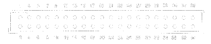
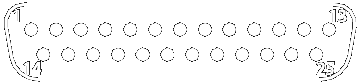
The serial interface uses a 25 pins D-SUB male Connector
| Pin | Name | Description |
|---|---|---|
 |
||
| 1 | SHIELD | Shield Ground. should not be connected to Ground |
| 2 | TXD | Transmit Data |
| 3 | RXD | Receive Data |
| 4 | RTS | Request to Send. |
| 5 | CTS | Clear to Send |
| 6 | DSR | Not Connected (Data Set Ready) |
| 7 | GND | System Ground |
| 8 | CD | Carrier Detect |
| 9-19 | N/C | |
| 20 | DTR | Data Terminal Ready |
| 21 | N/C | |
| 22 | RI | Ring Indicator |
| 23-25 | N/C |
Serial Interface Cables
Connection
to a modem uses a normal modem cable (e.g.
DB25F-DB25M or
DB25F-DB9M).
Connection to another computer (e.g. a PC) requires a null modem cable (e.g.
DB25F-DB25F or
DB25F-DB9F).
Plese refer to the RS232 Standard for description of these cables.
ATARI PARALLEL INTERFACE
 Printer Connector
The parallel interface also called the printer interface of the Atari is somewhat standard but is missing several standard signals found on PC's parallel interface (see description below).
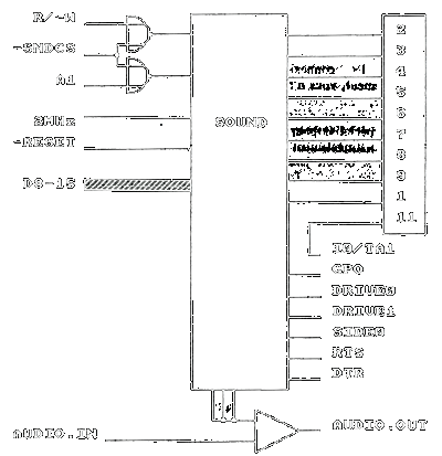
The printer signals are connected mostly on the Yamaha sound chip I/O ports! The only exception is the Busy signal that goes to input I0 of the MFP68901, and therefore a transition on this pin generates an interrupt.
The other signals shown in the schematic on the right are used in the Audio/Video Interface (audio in and out) , in the floppy disc interface (drive 0/1, side 0), and in the serial interface (RTS, DTR).
Back to the topPrinter Connector
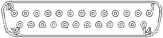
The Atari uses a standard 25 pins D-SUB Female connectors with the following pinouts (the last column showsa standard PC parallel interface connector for comparison).
| Pin | ST Connector | Standard PC Connector |
|---|---|---|
 |
||
| 1 | STROBE | STROBE |
| 2 | Data 0 | Data 0 |
| 3 | Data 1 | Data 1 |
| 4 | Data 2 | Data 2 |
| 5 | Data 3 | Data 3 |
| 6 | Data 4 | Data 4 |
| 7 | Data 5 | Data 5 |
| 8 | Data 6 | Data 6 |
| 9 | Data 7 | Data 7 |
| 10 | N/C | Acknowledge |
| 11 | BUSY | BUSY |
| 12 | N/C | Paper End |
| 13 | N/C | Select |
| 14 | N/C | Auto feed |
| 15 | N/C | Error |
| 16 | N/C | Initialize |
| 17 | N/C | Select In |
| 18 | GND | Signal Ground |
| 19 | GND | Signal Ground |
| 20 | GND | Signal Ground |
| 21 | GND | Signal Ground |
| 22 | GND | Signal Ground |
| 23 | GND | Signal Ground |
| 24 | GND | Signal Ground |
| 25 | GND | Signal Ground |
As you can see the Atari I/F is missing the signals on pins 10 and 12 to 17.
Back to the topPrinter Cables
It is possible to use a "standard printer cable" with the Atari. Many of the wires are not used due to the fact that several of the standard parallel port pins are not connected as already mentioned. Most printers from this time (like the EPSON LX800) where using a 36 CENTRONICS female connector. Therefore the most commonly used cable was the DB25M to CENTRONICS 36M printer cable.
Special Cables using the Printer Interface
The printer interface provides an easily programmable bidirectional interface to the external world and was therefore used in several projects.
Back to the topThe PARCP Cable
The printer interface is used by several solutions to provide a fast communication channel between two computers (up to 100KBds).
Several of these solutions are using the PARCP cable:
- The PARCP transfer program by Peter Stehlik (the origin of the name) [ ST/PC, ST/ST, PC/PC]
- ST-Trans © Atari 1992 [ST/ST ]
- Plip protocol of MiNT-Net © Kay Roemer
- HDD_DMN3 by MC Soft & Hard [ ST/PC ]
A description of this cable can be found at the PARCP site. it is basically a DB25M-DB25M data-switch cable (with all pins connected directly on both side) where the wires connected to pins 1 and 11 are switched on one end. This results to data signals connected bit to bit and strobe from one side connected to the busy on the other side plus of course the ground.
| Signal Name | DB25 | DB25 | Remark |
| Strobe / Busy | 1 | 11 | |
| Data 0 | 2 | 2 | 10K resistor can be inserted |
| Data 1 | 3 | 3 | 10K resistor can be inserted |
| Data 2 | 4 | 4 | 10K resistor can be inserted |
| Data 3 | 5 | 5 | 10K resistor can be inserted |
| Data 4 | 6 | 6 | 10K resistor can be inserted |
| Data 5 | 7 | 7 | 10K resistor can be inserted |
| Data 6 | 8 | 8 | 10K resistor can be inserted |
| Data 7 | 9 | 9 | 10K resistor can be inserted |
| N/C | 10 | 10 | Connected or not |
| Busy / Strobe | 11 | 1 | |
| N/C | 12-17 | 12-17 | Connected or not |
| Grounds | 18-25 | 18-25 | At least one on pin 25 |
FYI: I have successfully used the PARCP program with this cable, but I did not succeed with HDD_DMN3 program, and I did not try the other solutions (St-Trans and Plip).
Note that the data signals (pins 2 to 9) are connected to bidirectional ports on both side, and they are usually initialized to the default output mode (usually a printer is suppose to be connected to this port) with an unpredictable value (i.e. 0 or 1). Therefore it is possible that any particular data bit from an output on one side is at 0 and on that the output on the corresponding other side is at 1 (or vice-versa) resulting in an electrical conflict. Electronic interface circuits are relatively tolerant but this situation should be time minimized by either setting the ports into the input mode during startup of the computers (programs are provided as part of the PARCP solution for this matter), or by inserting a 1 KOhm to a 10 KOhm resistor between each data signals. For that matter a 8 x 10K resistor pack can be inserted inside a connector on one side.
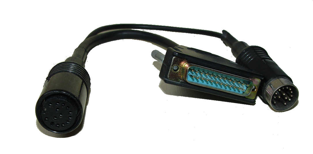
Back to the topThe BLITZ Cable
To create backup of "copy protected disk" the BLITZ solution uses a special cable and software to backup protected disk. You must have an external drive to use the BLITZ solution but there is no internal wiring or modification done to the computer. The BLITZ cable copies from drive 1 to drive 2 using at the same time the disk an printer interfaces (it reads Drive 1 and writes Drive 2 at the same time). The BLITZ solution allows to backup protected and non-protected disks.
To use the Blitz program you need an external floppy drive and a special cable. On one end you have a DIN14 female connector that is connected to the external floppy drive. From this connector you will have two cables: one going to a a DIN 14 male connector pluged into the Atari FD connector, and another one going to a D-SUB25 male connector that plug into the Atari parallel connector. Here is a picture of a blitz cable. The layout of the cable is the following:
 |
 |
|
| DIN14M @ Atari FD | DIN14F @ Ext. FD | DB25M @ Atari Parallel Interface |
| 1 - Read Data | ||
| 2 - Side 0 Select | 2 - Data 0 | |
| 3 - Logic Ground | 3 - Logic Ground | |
| 4 - Index Pulse | 9 - Data 7 | |
| 5 - Drive 0 Select | 3 - Data 1 | |
| 6 - Drive 1 Select | 3 - Data 1 | |
| 7 - Logic Ground | 20 - Ground (18-25) | |
| 8- Motor On | 7 - Data 5 | |
| 9 Direction In | 6 - Data 4 | |
| 10 - Step | 5 - Data 3 | |
| 1 - Read Data | 11 - Write Data | |
| 12 - Write Gate | 4 - Data 2 | |
| 13 - Track 00 | 11 - Busy | |
| 14 - Write Protect | 8 - Data 6 | |
| Shield | Shield | Shield |
ATARI DMA INTERFACE
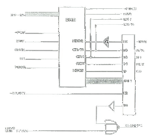
This interface allow to connect up to 8 external devices with a speed of up to 1MBytes / Sec. The interface is also called the Hard Disc interface because usually it it used to connect hard-disk, or the ASCI interface because it uses an Atari's proprietary hard drive connector/protocol similar to SCSI (which was standardized later) but unfortunately is not directly compatible.
The DMA interface takes its name from the fact that it is connected internally to one of the Atari specially design circuit: the DMA circuit.
The main signals are:
- A low asserted reset signal connected to the reset of the Atari
- A Chip Select CS
- An Address bit A1
- 8 bi-directional data bits Data 0 - Data 7
- The R/W signal (signal high = write, low = read),
- A low asserted Data Request input signal DRQ
- An acknowledge ACK
- An interrupt request signal that goes to input I5 of the MFP to generate an interrupt.
DMA / Hard disk connector
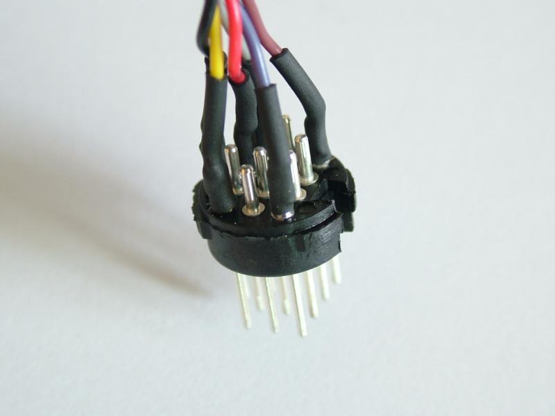
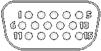
The DMA/Hard disk interface uses a very unusual and hard to find D-SUB 19 female connector.
 |
|
| Pin | Name |
| 1 | Data 0 |
| 2 | Data 1 |
| 3 | Data 2 |
| 4 | Data 3 |
| 5 | Data 4 |
| 6 | Data 5 |
| 7 | Data 6 |
| 8 | Data 7 |
| 9 | Chip Select |
| 10 | Interrupt Request |
| 11 | Ground |
| 12 | Reset |
| 13 | Ground |
| 14 | Acknowledge |
| 15 | Ground |
| 16 | A1 |
| 17 | Ground |
| 18 | Read/Write |
| 19 | Data Request |
Hard Disk Cable
To connect a hard disk like an Atari SH204/205 or a Megafile drive you will need to DB19M-DB19M Cable.
 |
|
| DB19M @ computer | DB19M @ Hard Disk |
All matching pins are directly connected from 1-1 to 19-19).
Back to the topATARI FLOPPY DISC INTERFACE
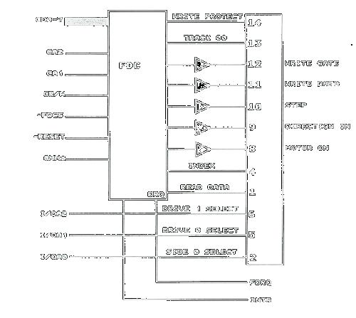 Floppy Disk Connector
As we will see the FD interface uses a very uncommon a hard to find DIN14 female connector. Most of the signals of this interface are connected to the Floppy disc controller chip (FDC) the Western Digital WD1772. Only few other signals are connected to the Sound circuit as shown in the parallel interface.
Back to the topFloppy Disc Connector
| Pin | Signal Name | FD Connector - DIN 14 Female |
| 1 | Read Data | |
| 2 | Side 0 Select | |
| 3 | Logic Ground | |
| 4 | Index Pulse | |
| 5 | Drive X Select | |
| 6 | Drive Y Select | |
| 7 | Logic Ground | |
| 8 | Motor On | |
| 9 | Direction In | |
| 10 | Step | |
| 11 | Write Data | |
| 12 | Write Gate | |
| 13 | Track 00 | |
| 14 | Write Protect |
The Atari owners's manual indicates that pin5 is Drive0 Select and pin 6 is Drive1 Select but in fact the signals connected to pin 5 and 6 depends upon the model (STE/STF) and position of internal strap(s) on the motherboard.
By default on both Atari STF and STE the straps on the motherboard are set so that Pin 5 is connected to signal Drive1 Select . This allows to see an external floppy drive, that uses the Pin 5 for selection, as drive B. So the internal drive is A and the external drive is B. This works with most external floppy drive for example a SF314/SF354 from Atari or a CSA354 from Cumana.
On an Atari STF there is one strap W2 that allow to change the signal that goes to pin 5.
- If the W2 strap is between pins 2-3 (the default) the signal connected to pin 5 is Drive1 Select.
- If the W2 strap is between pins 1-2 the signal connected to pin 5 is Drive0 Select.
- Note that the signal connected to pin 6 is always Drive1 Select.
On Atari STE it is more flexible because there are one strap W301 that allows to change the signal that goes to pin 5 and another strap W300 that allows to change the signal that goes to pin 6.
- If the W301 strap is between pin 2-3 (the default) the signal connected to pin 5 is Drive1 Select.
- If the W301 strap is between pin 1-2 the signal connected to pin 5 is Drive0 Select.
- If the W300 strap is between pin 2-3 (the default) the signal connected to pin 1 is logic 1 (drive never selected).
- If the W300 strap is between pin 1-2 the signal connected to pin 6 is Drive1 Select.
It is therefore important to verify that these internal straps are set to meet your requirements.
Floppy Disc Cable
Usually
external FD drive have a data cable coming out directly from the drive without
connector and terminated on the other side by a DIN14 male connector
that plug into the Atari FD interface.
In some cases it is necessary to use a DIN14M-DIN14M cable. This is the case for example with Discovery Cartridge where the cable is plugged on one side to the Atari FD connector and on the other side to Discovery Cartridge DIN14F connector labeled Computer. This cartridge is associated with a specific program allow to backup "copy protected disks". In this kind of cable all corresponding pins are connected directly: from pin 1-1 to pin 14-14 as well as the shield of each connector connected to the shield of the cable.
There is also a non standard cable to connect an external FD drive to an Atari called the BLITZ cable (described above).
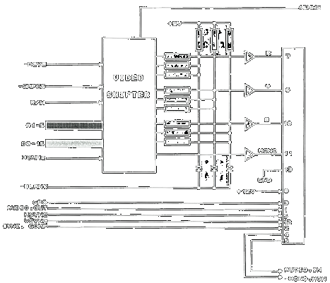
Back to the topATARI VIDEO INTERFACE
 Atari Television Connector
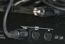
The Atari ST video signals are connected mainly to the Video Shifter circuitry as shown on the right side. The Audio out and GPO signals are connected from the Yamaha YM-2149 sound circuit, and the synchronization signals are coming from the Atari Glue chip.
For an Atari STE the video circuitry has been changed. However it stays close to the ST. Plese refer to the STE Hardware page for more information. For more information about the Atari video and how to connect moder monitor please refer to my Atari ST video page.
Back to the topAtari Television Connector
Some Atari models have an RF modulator included (e.g. 520STFM) in this case they are equiped with a special connector for TV. You just need to connect this output to your TV antenna and to tune your TV. This output can also be used with a special box to connect to a VGA monitor.
|
 |
||||
| TV Pinout | TV Out Connector |
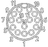
Atari Video Connector
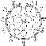
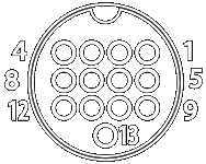
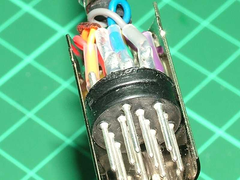
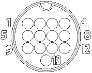
The Video connector used on the Atari is a rather unusual and very hard to find 13 DIN Female connector. This connector carry out all the video signals (RGB and Sync) as well as audio in and out and a general purpose output pin. The following table shows the pin-out of the Atari 13 DIN Female video connector from the front (external) side. This pictures show DIN13 female connectors and male connector.
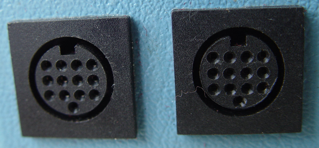
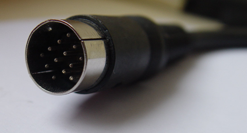
PIN |
NAME |
 |
|
1 |
Audio out (ST/STE): |
2 |
Composite Sync / Video (STE only):
|
3 |
General Purpose Output (ST): |
4 |
Monochrome detection (ST/STE): |
5 |
Audio in (ST/STE): |
6 |
Green (ST/STE): |
7 |
Red (ST/STE): |
8 |
12V / 10mA pin (STE) : On STE this pin is connected to 12V. |
9 |
Horizontal synchronization (ST/STE): |
10 |
Blue (ST/STE): |
11 |
Monochrome (ST/STE): |
12 |
Vertical synchronization (ST/STE): |
13 |
Ground |
Atari Video cables
Cables Quality
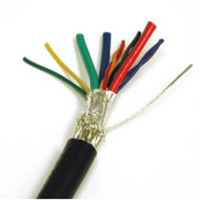
It is important to use good quality cables to carry the video. The cable must be at least shielded externally, and the color / mono signals should preferably use coaxial wire (especially for long cable like SCART).
Here is an example of a good cable to connect to the Atari DIN13 video output connector. The cable is constructed from three 28 AWG (75 Ohm) coaxial cables plus three 26 AWG twisted pairs and two 26 AWG conductors to ensure signal integrity. Coax cables feature a tinned copper braid providing 93% shield. The cable is shielded by a tinned copper braid providing a minimum of 85% coverage, Mylar® aluminum foil and drain wire to provide 100% coverage.
As pins on the Mini-DIN 13 connector are very packed it is therefore recommended to use heat-shrink tubes for proper isolation of each pin.
The shield(s) of the cable and eventually coaxial cables need to be connected to pin 13 of the DIN connector.
Back to the topSCART/Peritel Cable
This cable allows to connect an Atari, operated in color low/medium resolution, to a TV equipped with a SCART/Peritel input connector. The cables use on one side a DIN13 Male connector and on the other side it uses a male SCART connector. Both connectors are shown from front side and not from solder side
| Signal Name | DIN13 male | SCART male | Remark |
 |
 |
||
| Audio Out | 1 | 6+2 | Audio Left & Right |
| Composite Sync | 2 | 20 | Composite sync |
| Monochrome Detect | 4 | Must be left open | |
| Green | 6 | 11 | Green in (through 150 Ohms resistor) |
| Red | 7 | 15 | Red in (through 150 Ohms resistor) |
| 12V Pullup | 8 | 8 | Audio/RGB Switching |
| Blue | 10 | 7 | Blue in (through 150 Ohms resistor) |
| V-Sync | 12 | 16 | Blanking signal |
| GND | 13 | 4+5+9+13+17+18+21 | Ground |
Notes:
- If the colors are washed out it is recommended to connect the RGB / Sync signals through 150 Ohms resistors to drop voltage from 1v to 0.7v. On an Atari the RGB output signals already pass through 27 Ohms resistors on an STF and 75 Ohms resistors on an STE, and therefore in most cases these resistors are not required. It is also recommended to connect the Blanking signal through a 75 Ohms resistor. The V-Sync output signals already pass through 33 Ohms resistors and therefore in most cases this resistor is not required. Most of the cables you buy in the commerce do not have any of these pass-through resistors.
- Connection of the audio out from Atari to pin 2 is not mandatory as pin 6 is the mono input.
- Some people only connect Atari GND (P13) to SCART P21. I believe that it is better to also connect pin 4, 5, 9, 13, 17, and 18.
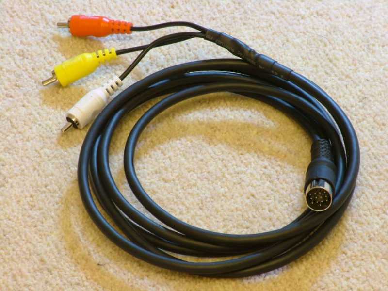
RCA Composite Video Cable
This cable is useful if you have an Atari ST equiped with an RF modulator. In that case the Atari produces on pin 2 of its video connector a composite video signal (instead of a composite sync signal). It is therefore possible to use this signal on an equipement that have an RCA composite video signal input (the Yellow or phono input -- see here) like for example the Supera Color HD Box. The White and Red audio RCA plugs are connected to the audio output of the Atari. Here is an example of a RCA Composite video cable.
| Signal Name | DIN13 male | RCA Plugs | Remark |
|
|||
| Audio Out | 1 | Red & White | Audio to Red and White RCA plugs |
| Composite Sync | 2 | Yellow | Composite video to Yellow RCA plug |
| Monochrome Detect | 4 | Must be left open | |
| Ground | 13 | Shields | The shield of all RCA cables should be connected to the Atari Ground |
If the colors are washed out it is recommended to connect the RGB / Sync signals through 150 Ohms resistors to drop voltage from 1v to 0.7v.
Back to the topVGA Monochrome Cable
This cable allows to connect an Atari, operating in High-resolution monochrome mode, to a VGA/SVGA Monitor. The cable uses on one side a DIN13 male connector and on the other side a D-SUB15 male VGA connector . The Atari is automatically set to Hi-resolution mode when this cable is connected (pin 4 set to ground). Note that if you want to hear the sound from the Atari you need an extra audio cable (connected to pin 1) going to an audio connector (e.g. a mini jack or RCA connector).
| Signal Name | DIN13 male | DB15 male | Remark |
|
 |
||
| Audio Out | 1 | Opt. Audio connector | |
| Monochrome Detect | 4+13 | 4 Connects to pin 13 | |
| H-Sync | 9 | 13 | |
| Monochrome | 11 | 1+2+3 | |
| V-Sync | 12 | 14 | |
| GND | 13 | 6+7+8+10 |
VGA Color Cable
This cable allows to connect an Atari, running in Med-Low resolution color mode, to a VGA/SVGA monitor. The cables use on one side a DIN13 male connector connected to the Atari and on the other side a D-SUB15 male VGA connector connected to the monitor. The Atari is automatically set to Med/Low-resolution mode (pin 4 left open). Note that if you want to hear the sound from the Atari you need an extra audio cable (connected to pin 1) going to an audio connector (e.g. a mini jack or RCA connector).
Important notice: This solution only works if your monitor accepts a 15.75 kHz Horizontal sync (see Connecting Modern LCD/CRT Monitors to an Atari for the video signals charateristics).
| Signal Name | Atari | DB15 | Remark |
|
|
||
| Audio Out | 1 | Audio connector | |
| Monochrome Detect | 4 | Open | |
| Green | 6 | 2 | |
| Red | 7 | 1 | |
| H-Sync | 9 | 13 | |
| Blue | 10 | 3 | |
| V-Sync | 12 | 14 | |
| GND | 13 | 5+6+7+8+10 |
VGA9 Monochrome Cable for multisync monitor
This cable allows to connect an Atari, running in High resolution monochrome mode, to a multisync monitor using a VGA9 DB9 connector. The cables use on one side a DIN13 male connector connected to the Atari and on the other side a D-SUB9 male connector connected to the monitor. The Atari is automatically set to Hi-resolution mode. Note that if you want to hear the sound from the Atari you need to have a separate audio cable going to an audio connector (e.g. a mini jack or RCA connector).
Important notice: The cable described here is for a VGA9 Multisync type of Monitor (like the NEC Multisync II JC 1402HME) but it is NOT for a standard EGA/CGA (with different pinout) type of monitor (see VGA9/EGA/CGA DB9 Connector).
Signal Name |
Atari |
DB9 |
Remark |
|
 |
||
Audio Out |
1 |
|
Opt. Audio Signal |
Composite Sync/Video |
2 |
|
|
Monochrome Detect |
4+13 |
|
Connect to Atari pin 13 |
H-Sync |
9 |
4 |
|
Monochrome |
11 |
1+2+3 |
|
V-Sync |
12 |
5 |
|
GND |
13 |
6+7+8+9 |
Opt. Audio GND |
VGA9 Color Cable for multisync monitor
This cable allows to connect an Atari, running in Medium-Low resolution color mode, to a VGA multisync monitor with a VGA9 DB9 connector. The cables use on one side a DIN13 Male connector connected to the Atari and on the other side a DB9 male connector connected to the monitor. The Atari is automatically set to Med/Low resolution mode. Note that if you want to hear the sound from the Atari you need to have a separate audio cable going to an audio connector (e.g. a mini jack or RCA connector).
Important notice: The cable described here is for a VGA9 Multisync type of Monitor (like the NEC Multisync II JC 1402HME) but it is NOT for a standard EGA/CGA (with different pinout) type of monitor (see VGA9/EGA/CGA DB9 Connector). Also this solution only works if your monitor accepts a 15.75 kHz Horizontal sync (see Connecting Modern LCD/CRT Monitors to an Atari for the video signals charateristics)
Signal Name |
Atari |
DB9 |
Remark |
|
|
||
Audio Out |
1 |
|
Opt. Audio Signal |
Composite Sync/Video |
2 |
|
|
Monochrome Detect |
4 |
|
Open |
Green |
6 |
2 |
|
Red |
7 |
1 |
|
H-Sync |
9 |
4 |
|
Blue |
10 |
3 |
|
V-Sync |
12 |
5 |
|
GND |
13 |
6+7+8+9 |
Opt. Audio GND |
Atari Video Switchers
Atari Monitors Switch box
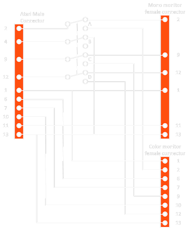
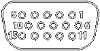
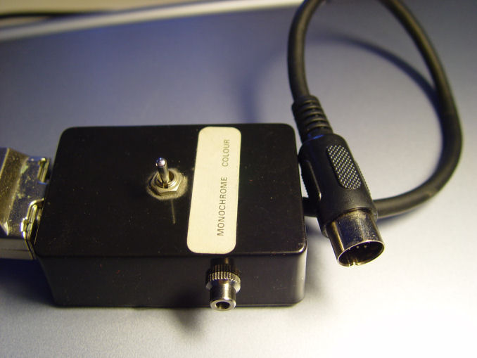
If you have an Atari SM124 High resolution monochrome monitor as well as an Atari SC1224 color monitor then it is a good idea to use an Atari monitor switcher. This will allow you to switch from one monitor to the other without plugging/unplugging cables. You need a four circuits toggle switch and an enclosure (preferably a metal one) as well as a male DIN13 connector for the cable and two female DIN13 connectors to put on the enclosure. The four circuits of the toggle switch are called A, B, C, D with the input being "in" and the output "1" & "2". For example Ain is connected to A1 if switch is in position 1 and to A2 if switch is in position 2 and of course the four circuits toggle at the same time. This picture show an example of this kind of video switch.
| Signal Name | Male to Atari | Mono connector | Color connector |
|
|
|
|
| Audio Out | 1 | 1 | 1 |
| Composite Video | 2+Ain | 2+A1 | 2+A2 |
| General Purpose Output | |||
| Monochrome Detect | 4+Bin | ||
| Audio - in | |||
| Green | 6 | 6 | |
| Red | 7 | 7 | |
| 12 Volts pullup | |||
| Horizontal Sync | 9+Cin | 9+C1 | 9+C2 |
| Blue | 10 | 10 | |
| Monochrome | 11 | 11 | |
| Vertical Sync | 12+Din | 12+D1 | 12+D2 |
| GND | 13+B1 | 13 | 13 |
Position1 is the monochrome mode, position 2 is color mode. In summary the connection are:
- RGB & Audio & GND are always connected from the input connector to the color output connector
- Mono & Audio & GND are always connected from the input connector to the monochrome output connector
- Composite Synch, H-Sync, and V-Sync are switched from the input connector to the mono or color monitor outputs depending of switch position
- Monochrome detect of the input connector is switched to ground in monochrome position and left open in color position
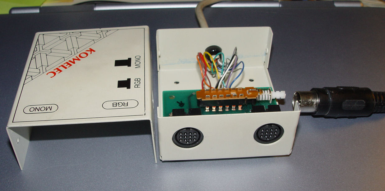
Multisync Switch box
If you own a NEC Multisync II JC-1402HME or equivalent you can build a special multisync switch box that allows you to directly switch between the two modes (mono/color) just by flipping a switch. You need a box (preferably a metal box), a four pole double throw toggle switch, an Atari DIN13 male connector, a video cable, and a female DB15 connector. The Atari DIN13 male connector is connected to the video cable that goes into the box on one side, on the other side you have the DB15 female connector. The four circuits of the toggle switch are called A, B, C, D with the input being "in" and the output "1" & "2". For example Ain input is connected to A1 output if switch is in position 1 and to A2 output if switch is in position 2. The four circuits of the switch toggle at the same time. If you want to hear audio you also need to add an audio connector on the side of the box.
| Signal Name | connect to atari | DB15F @ box | Remarks |
|
 |
||
| Audio Out | 1 | audio connector |
|
| Monochrome Detect | 4+A1 | ||
| Green | 6+B2 | 2+Bin |
|
| Red | 7+C2 | 1+Cin |
|
| Horizontal Sync | 9 | 13 | |
| Blue | 10+D2 | 3+Din | |
| Monochrome | 11+B1+C1+D1 | ||
| Vertical Sync | 12 | 14 | |
| GND | 13+A1 | 5+6+7+8+10 |
Position 1 is for monochrome mode, position 2 is for color mode. In summary the connection are:
- Audio goes to an audio connector fixed on the enclosure
- H-Sync, V-Sync, and GND from Atari are always connected to H-Sync, V-Sync, and GND of monitor input connector
- RGB outputs from Atari are connected to RGB inputs of monitor in color position
- Monochrome output from Atari is connected to the RGB inputs of monitor in monochrome position
- Monochrome detect of the Atari is connected to ground in monochrome position and left open in color
You to connect a recent monitor with a standard DB15M-DB15M cable or you can connect a NEC JC-1402HME Multisync monitor with a special DB15M-DB9M (VGA type) cable/adapter. But remember that this solution only works if your monitor accepts a 15.75 kHz Horizontal sync (see Connecting Modern LCD/CRT Monitors to an Atari for the video signals charateristics).
Example Pictures (internals, closed) of the switch I made for my Nec Multisync II monitor (note the connector for sound output)
Back to the top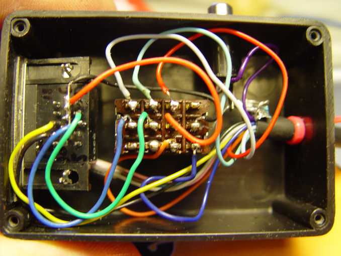
ATARI MOUSE/JOYSTICK INTERFACE
- The Keyboard and mouse/joystick Interface
- The mouse/joysticks connectors
- Mouse/Joysticks Switch
- Mouse Replacement
The Keyboard Interface
 |
 |
Also not accessible from the outside the keyboard is connected to the main board through a connector. The keyboard, mouse, and joysticks are handled by a dedicated processor the 6301 that includes an internal ROM and RAM. The schematic of the keyboard shows how the keys and the mouse/joystick connectors are connected to the microprocessor. The keyboard communicate with the main system through a serial interface a 6850 ACIA.
Back to the topThe Mouse/Joystick Connectors
The Atari ST has two connectors under the keyboard to connect a mouse or joystick (port 0) and a second joystick (port 1)
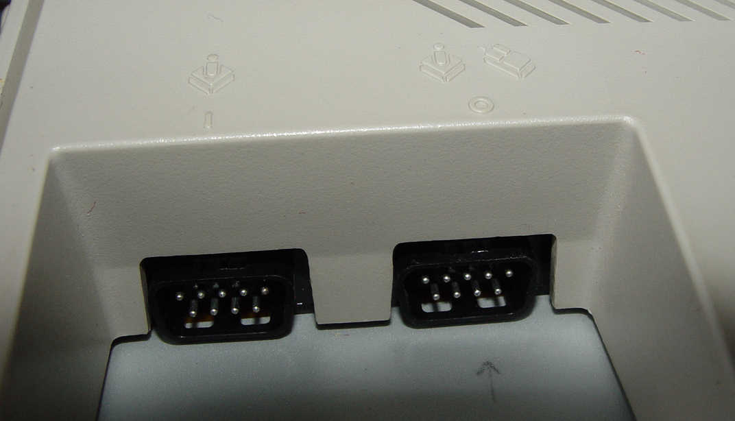
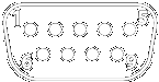
The two connectors are DB9M connectors
|
|
| Mouse/Joystick - Port 0 | Joystick - Port 1 |
| 1 - Up / XB | 1 - Up |
| 2 - Down / XA | 2 - Down |
| 3 - Left / YA | 3 - Left |
| 4 - Right / YB | 4 - Right |
| 5 - NC | 5 - Reserved |
| 6 - Fire / Left Button | 6 - Fire Button |
| 7 - +5VDC | 7 - +5VDC |
| 8 - Ground | 8 - Ground |
| 9 - Joy 1 Fire/Right Button | 9 - NC |
Mouse/Joystick Switch
Accessing the mouse/joystick connectors is not easy as it is located under the keyboard. However as all programs uses a mouse and most games uses the joystick it is necessary to unplug the mouse and plug the joystick each time you want to play a game and vice-versa. This is obviously not very practical and therefore it is recommended to buy a mouse/joystick switch that allow to connect permanently two joysticks and a mouse and to select with a switch between the mouse and joystick on port 0. This following picture shows this kind of switch.
Back to the top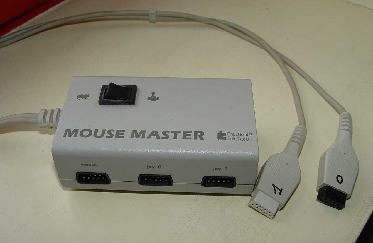
Mouse Replacement
TODO : PeST & serial
ATARI STE STEREO AUDIO INTERFACE
The Atari STE has two RCA Audio output ports for stereo (labeled left and right).
ATARI STE JOYSTICK INTERFACE
The Atari STE has two joystick DB15F connectors on the left side of the system.
|
|
| Port A | Port B |
| 01 - Up 0 | 01 - Up 1 |
| 02 - Down 0 | 02 - Down 1 |
| 03 - Left 0 | 03 - Left 1 |
| 04 - Right 0 | 04 - Right 1 |
| 05 - PAD 0 Y | 05 - PAD 1 Y |
| 06 - Fire 0 Button | 06 - Fire 1 Button |
| 07 - VCC (5V) | 07 - VCC (5V) |
| 08 - NC | 08 - NC |
| 09 - Ground | 09 - Ground |
| 10 - Fire 2 Button | 10 - Fire 3 Button |
| 11 - Up 2 | 11 - Up 3 |
| 12 - Down 2 | 12 - Down 3 |
| 13 - Left 2 | 13 - Left 3 |
| 14 - Right 2 | 14 - Right 3 |
| 15 - Pad 0 X | 15 - Pad 1 X |
Here you will find an interesting usage of these ports to connect to a PC. From Leonard Site (SainT)
Back to the topSTANDARD CONNECTORS / ADAPTORS / CABLES (Non-Atari Specific)
This section presents several connectors/adaptors which are non specific to Atari but useful.
- SCART/Peritel Connector
- VGA DB15 Connector
- EGA/CGA/VGA9 DB9 Connector
- S-Video Connector
- DB15 - DB9 (VGA9 type) Adaptor/Cable
- DB15 - DB9 (CGA/EGA type) Adaptor/Cable
- SCART to S-Video / Composite Adapter
SCART/Peritel Connector
|
 |
| SCART male | SCART female |
| Pin | Name | Description | Signal Level | Impedance |
|---|---|---|---|---|
| 1 | AOR | Audio Out Right | 0.5 V rms | <1k ohm |
| 2 | AIR | Audio In Right | 0.5 V rms | >10k ohm |
| 3 | AOL | Audio Out Left + Mono | 0.5 V rms | <1k ohm |
| 4 | A GND | Audio Ground | ||
| 5 | B GND | RGB Blue Ground | ||
| 6 | AIL | Audio In Left + Mono | 0.5 V rms | >10k ohm |
| 7 | B | RGB Blue (S-Video Cup / Pb) | 0.7 V | 75 ohm |
| 8 | SWTCH | Status & Aspect Ratio | 0-0.4V=off, 5-8V=16:9, 9.5-12V=on 4:3 |
|
| 9 | G GND | RGB Green Ground | ||
| 10 | CLKOUT | Data 2 / Clock | ||
| 11 | G | RGB Green In | 0.7 V | 75 ohm |
| 12 | DATA | Data 1/ Reserved | ||
| 13 | R GND | RGB Red Ground | ||
| 14 | DATAGND | Data Ground | ||
| 15 | R | RGB Red (S-Video Cdown / Pr) | 0.7 V (Chrom.: 0.3 V burst) | 75 ohm |
| 16 | BLNK | Blanking Signal | 1-3 V=RGB, 0-0.4 V=Composite | 75 ohm |
| 17 | VGND | Composite Video Ground | ||
| 18 | BLNKGND | Blanking Signal Ground | ||
| 19 | VOUT | Composite Video Out (S-Video Yout) | 1 V | 75 ohm |
| 20 | VIN | Composite Video In / (S-Video Yin) | 1 V | 75 ohm |
| 21 | SHIELD | Ground/Shield (Chassis) |
Note: information between parentheses is for non standard extensions.
Back to the topVGA DB15 Connector
This is the standard VGA Connector used by most monitors. Information can be found here
|
|
| DB15 male | female @ video card |
| Pin | Name | Description |
|---|---|---|
| 1 | RED | Red Video (75 ohm, 0.7 V p-p) |
| 2 | GREEN | Green Video (75 ohm, 0.7 V p-p) |
| 3 | BLUE | Blue Video (75 ohm, 0.7 V p-p) |
| 4 | ID2 | Monitor ID Bit 2 |
| 5 | GND | Ground |
| 6 | RGND | Red Ground |
| 7 | GGND | Green Ground |
| 8 | BGND | Blue Ground |
| 9 | KEY | Key (No pin) |
| 10 | SGND | Sync Ground |
| 11 | ID0 | Monitor ID Bit 0 |
| 12 | ID1 or SDA | Monitor ID Bit 1 |
| 13 | HSYNC or CSYNC | Horizontal Sync (or Composite Sync) |
| 14 | VSYNC | Vertical Sync |
| 15 | ID3 or SCL | Monitor ID Bit 3 |
EGA/CGA/VGA9 DB9 Connectors
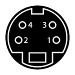
These standards have been used on very old monitors. Note that there are two totally incompatible DB9 standards:
- The VGA9 standard has been used mainly for Multisync JC-1402HME type of monitors and
- The EGA/CGA has been used on early IBM machines / monitors.
|
|
| Male @ monitor cable | female @ video card/monitor |
Pin |
Name |
EGA Description |
CGA Description |
VGA9 Description |
1 |
GND |
Ground |
GND |
Red |
2 |
SR |
Secondary Red |
GND |
Green |
3 |
PR |
Primary Red |
Red |
Blue |
4 |
PG |
Primary Green |
Green |
Horizontal Sync / Composite Sync |
5 |
PB |
Primary Blue |
Blue |
Vertical Sync |
6 |
SG/I |
Secondary Green / Intensity |
Intensity |
Red GND |
7 |
SB |
Secondary Blue |
Reserved |
Green GND |
8 |
H |
Horizontal Sync |
Horizontal Sync |
Blue GND |
9 |
V |
Vertical Sync |
Vertical Sync |
Sync GND |
S-Video Connector
 This connector (Ushiden connector) is used to carry the S-Video signals.
Pin |
Signal Name |
Remarks |
1 |
GND |
Ground Y |
2 |
GND |
Ground C |
3 |
Y |
Intensity (luminance) |
4 |
C |
Color (Chrominance) |
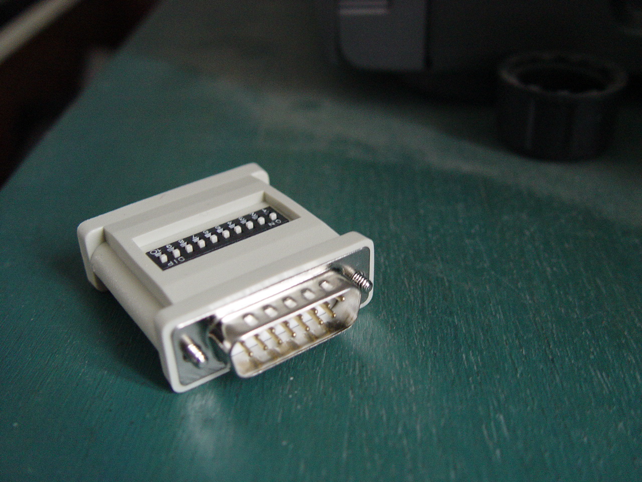
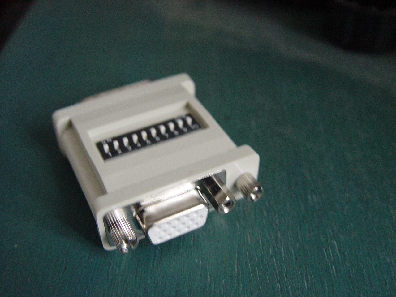
DB15 to DB9 (VGA9 type) Adaptor/Cable
This can either be an adaptor (usually DB15 male to DB9 Female) or a cable (DB15 male to DB9 male) which is used to connect an old VGA9 monitor with a DB9 female input to the output from a computer with standard VGA DB15 female connector. See pictures here and here.
| Signal Name | DB9 | DB15 |
 |
|
|
| Red | 1 | 1 |
| Green | 2 | 2 |
| Blue | 3 | 3 |
| H-Sync | 4 | 13 |
| V-Sync | 5 | 14 |
| GND | 6+7+8+9 | 5+6+7+8+10 |
DB15 to DB9 (CGA/EGA type) Adaptor/Cable
This can either be an adaptor (usually DB15 male to DB9 Female) or a cable (DB15 male to DB9 male) which is used to connect an old VGA9 monitor with a DB9 female input to the output from a computer with standard VGA DB15 female connector. See pictures here and here.
| Signal Name | DB9 | DB15 |
|
|
|
| Red | 3 | 1 |
| Green | 4 | 2 |
| Blue | 5 | 3 |
| H-Sync | 8 | 13 |
| V-Sync | 9 | 14 |
| GND | 1+2 | 5+6+7+8+10 |
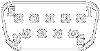
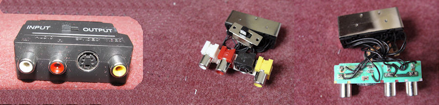
SCART to S-Video / Composite Adapter
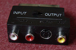 This adapter is used to convert from/to SCART to/from S-Video or Composite. It is usually provided as a box with a 3 circuits switch, one or two SCART connector(s), a S-Video connector, 3 RCA composite connectors (Yellow, Red, White). The 3 circuits of the toggle switch are called A, B, C with the input being "in" and the output "1"& "2". For example Ain input is connected to A1 output if switch is in position 1 and to A2 output if switch is in position 2.
Signal Name |
SCART |
S-Video (Y/C) |
RCA (Y / R / W) |
Audio out(right) |
1 + C1 |
|
Red + CIN |
Audio in (right) |
2 + C2 |
|
|
Audio out (left) |
3 + B1 |
|
White + BIN |
Audio out (right) |
6 + B2 |
|
|
Audio GND |
4 |
|
GND (White + Red) |
RGB GND |
13 |
2 (GND C) |
|
RGB Red / S-Video C |
15 |
4 (C) |
|
GND |
17 + (18) |
1 (GND Y) |
GND (Yellow) |
Composite / S-Video Y |
|
3 (Y) + AIN |
Yellow |
(Composite / S-Video) OUT |
19 + A1 |
|
|
(Composite / S-Video) IN |
20 + A2 |
|
|
Position 1 is Output (SCART to S-Video), Position 2 is Input
Audio on RCA (Red and White) are switch from/to SCART Audio in or out Composite on RCA (Yellow) is switched from/to SCART Composite in or out S-Video Color (4) is always connected to SCART Red / S-Video C out S-Video Y Luma (3) is switched from/to SCART S-Video Y in or out.
It is highly not recommended to open this kind of video adaptor. Plastic is sealed and breaks during opening and wires are very fragile. See an opened adapter below.
Useful LINKS
Some links to sites that provide useful information ...
- Handbook of hardware pinouts, cables schemes and connectors layouts - When searching information about connectors and cables this is the first place to visit. However beware that there are several errors concerning Atari (for example the FD connector...)
- HwB The Hardware Book - Excellent site for Connectors / Cables / Adapters
- NullModem.Com - Useful information on building you own cable
- Data cable information - Cables for data interfacing
- Atari Cable document. - Text document from unknown source that provided lots of information.
- NEC MULTISYNC Model JC-1402HME/EE/ED/N/R Service Manual