![]() Version Française suivre ce lien
Version Française suivre ce lien
This page detailed the disassembly and reassembly of Atari STE and STF and HDD SH 205/20 Megafile.
Note that all the images on this page are thumbnails and to view the full size detailed picture simply click on the thumbnail.
- Disassembling Atari computers
- Disassembling the SH 205 Hard Disk (French only)
Disassembling Atari 520/1040 STE & STF
This section explains how to completely disassemble a 1040/520 Atari STE / STF computer.
Depending on what you have to do (for example, changing power supply, adding memory, etc.) it is obviously not always necessary to remove everything ... but if the need arises all information is there!
Disassembly is presented following a logical order: from opening the plastic enclosure to the ultimate "undressing" of the motherboard.
The reassembly of the computer is not detailed as you just have to follow the diassembly procedure in reverse order. However, a summary is provided for this purpose.
- Removing the Atari Enclosure
- Removing the Keyboard
- Removing Power supply & Memory shield
- Removing Atari STE SIMM Memories
- Removing the Floppy Disk Drive
- Removing the electronic assembly
- Removing the power supply
- Removing the shield covering the motherboard
- Complete reassembly of the computer
Removing the Atari Enclosure
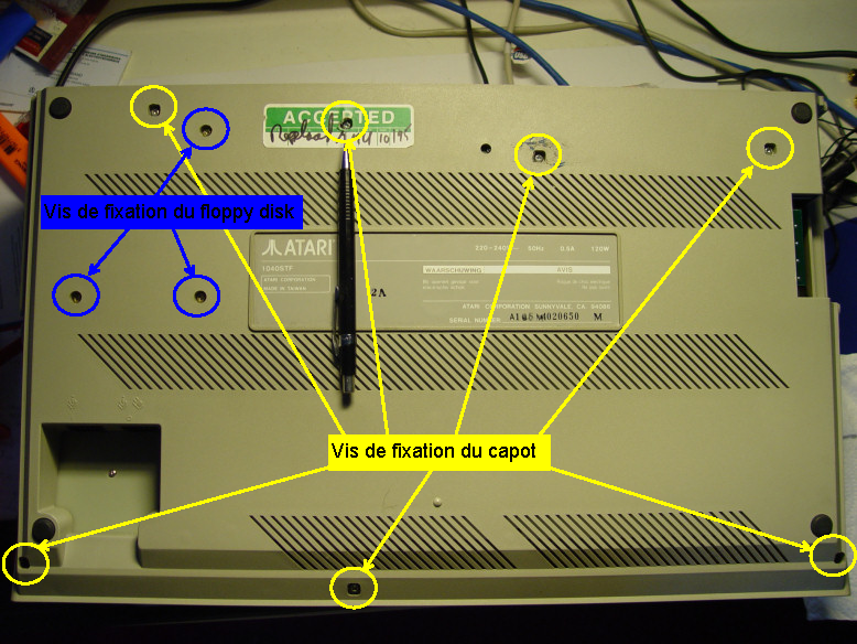 Flip the computer upside down and locate the screws securing the cover. As shown in the photo, it is held by three screws at the bottom edge of the keyboard and four screws along the top edge. The 2nd top screw (marked by the tip of the pen on the photo) can be masked by a label. This label is a seal which indicates an intact system that has never been opened. It is reported that if you break the seal it will result in immediate termination of the warranty ... But of course this is not really important nowadays. I recommend that you pinpoint the location of the screws you remove, so that you can put back the same screws in the same locations. Check especially the difference between the top screws and the bottom screws because, in theory, they do not have the same lengths. For the moment, remove only the cover screws but do not remove the floppy drives crews .

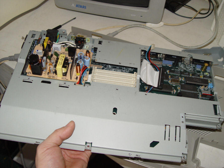
 Holding both halves of the case together, flip the computer back over and carefully free the upper casing from the lower portion. To do this, first lift the cover from the left as shown in the pictures. Depending on your Atari this can be very easy or more difficult. After removing the cover you should see the keyboard at the bottom and several metal shields and the floppy drive at the top.

 The left photo shows a 520STE Atari and the right photo Atari 1040STF. You will notice that the right cover (above the floppy disk) is slightly different on the two models, but that the left cover is radically different. In an Atari STE the shield covers the power supply and the memory modules, whereas in the the Atari STF the shield only covers the power supply.
Back to the top
Removing the Keyboard
This is especially simple, but be careful not to damage the wires of the keyboard.
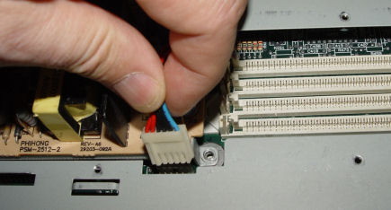
The keyboard rests without being attached to the bottom of the chassis and is therefore sufficient to lift and move it to access the connector.
 Now just unplug this connector to completely remove the keyboard. This operation can be a little tricky, because usually this connector is hard to remove. Make sure you pull the plug and not the wires! It is therefore recommend to pull the connector with a flat pliers.
Note that it is not necessary to remove the keyboard to install memory, but it's still recommended.
Now just unplug this connector to completely remove the keyboard. This operation can be a little tricky, because usually this connector is hard to remove. Make sure you pull the plug and not the wires! It is therefore recommend to pull the connector with a flat pliers.
Note that it is not necessary to remove the keyboard to install memory, but it's still recommended.
Removing the Power Supply & Memory shield
As we have seen in the case of Atari 520/1040 STE the shield covers both the power supply and the memory modules and in the case of Atari 520/1040 STF the shield covers only the power supply.
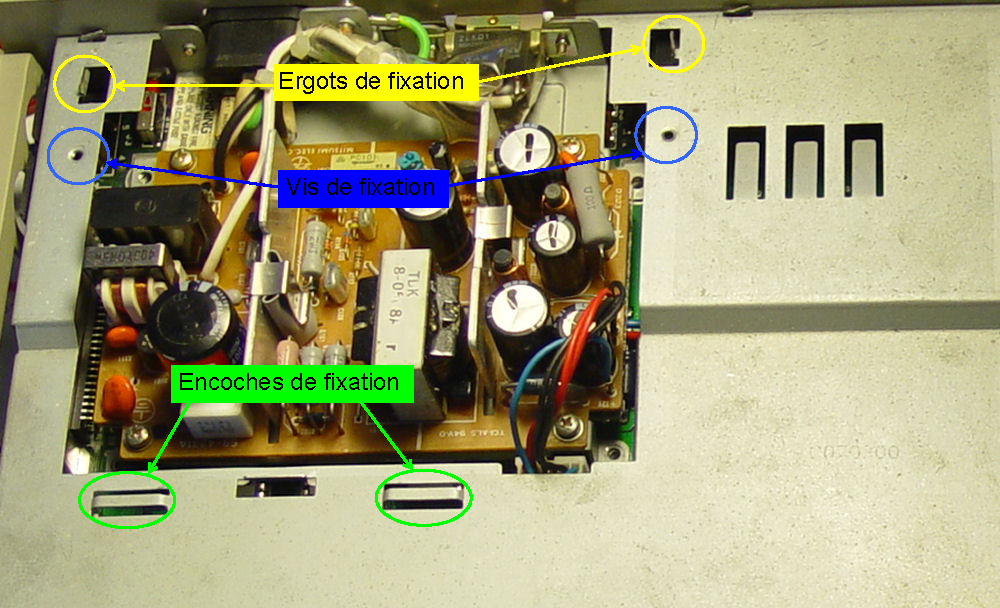
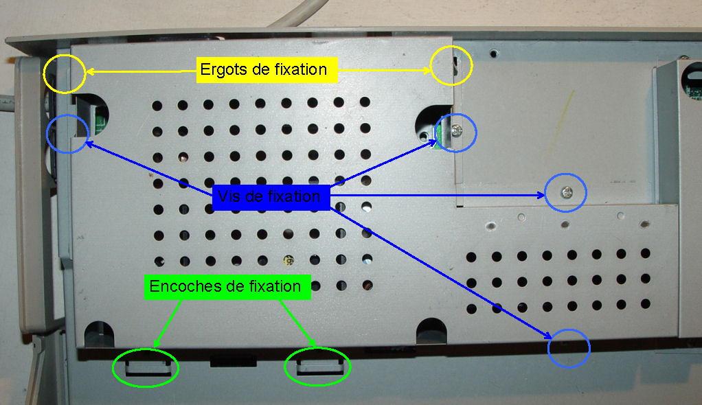 We will first consider the case of 520/1040 STE. The pictures on the left shows the metal shield and placement of screws , the fixation lugs
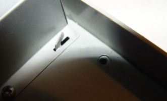
Start by removing the screws. Do not worry if you do not have the number of screws shown in the figure in theory there should be four, but one or two are quite sufficient, because the cover is held by the fixation lugs. Once the screws have been removed, we must now untwist the "fixation lugs". For this operation you need to use a flat pliers: untwist the lugs until they are aligned with the slot below. The following pictures show a fixation lug before, during, and after "surgery".
 |
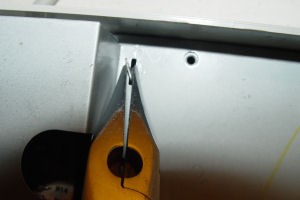 |
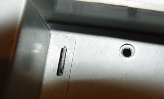 |
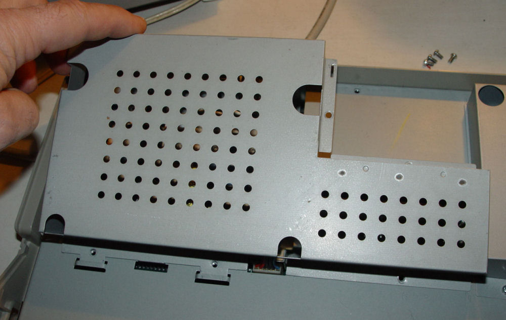
 Once you have untwisted the two fixations, you simply tilt the cover towards you because it is still held by the mounting slots at the bottom.
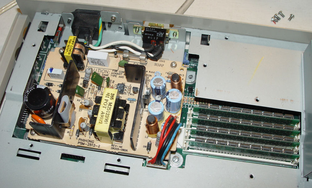
Once the cover is removed it gives you access to the memory and the power supply.
 Disassembly for Atari STF is all quite similar just the hood is smaller and has only two screws as shown in this picture.
Removing Atari STE SIMM Memories
This only applies to Atari STE model because STF are equipped with fixed memory located directly on the motherboard.
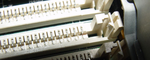

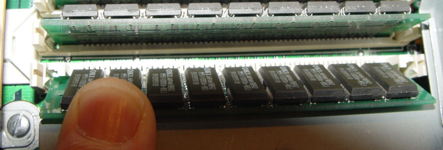
The memory modules are held on each side by a spring clug. Pull the locking spring clugs on both sides outward to enable the SIMM to rock forward. The SIMM will not release unless the clugs have cleared the back of the SIMM. Once the SIMM is tilted to an angle of about 45 degrees, you can remove it by pulling toward you. You will find here interesting information about configurations and installation of memory modules.
Back to the topRemoving the Floppy Drive
 The first step is to remove the shield that protects the connectors of the drive. For that it suffices to remove the two screws and pull the cover that is clamped onto the drive.
You must now return the system and remove the three screws that secure the drive pictured in removing the enclosure . Return the system upside-down, taking care to hold the drive because it is no more fixed.
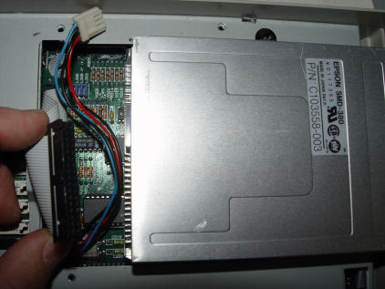
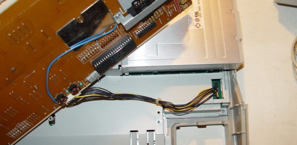
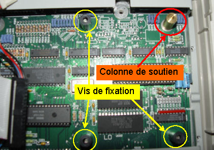 You must now remove the power connector and the data connector. Please note these two connectors are difficult to remove and as usual care must be taken not to pull hard on the wires. It is now possible to remove the drive. Note the location of the 3 screws and the support column.
Removing the electronic assembly
This operation involves removing the entire electronic assembly from the lower plastic enclosure. This is usually needed to remove the power supply from STE system. I say usually because for some STF and STE you can remove the power without removing the assembly.
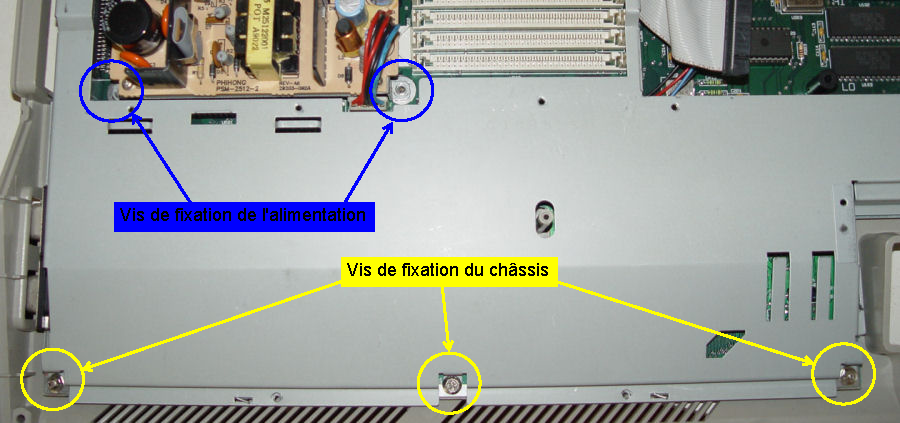 To remove this ensemble you must remove the two screws holding the power supply and the three screws at the bottom of the assembly. Be careful the screws holding the power supply are those located at the "bottom" on the metal lugs and not the screws that secure the PCB of the power supply.
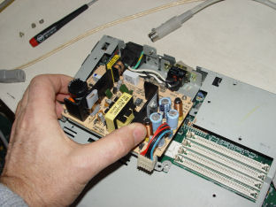
 Once these five screws are removed you can take away the assembly from the plastic enclosure. This is very easy on the Atari STF but is harder on Atari STE due to the presence of the two digital joystick connectors on the left of the assembly. It is sometimes necessary to pull slightly to the left of the plastic enclosure to release these connectors.
Removing the Power Supply
 As stated above it is often necessary to remove the assembly from the bottom of the plastic enclosure to remove the power supply of the STE because it is difficult to tilt the power on some models that have a shield on the back.
If you have already removed the chassis you just have to unplug the power connector, otherwise you must first remove the two screws as indicated above..
Removing the shield covering the motherboard
If you need to access the motherboard to fix/modify your system you have to remove the shield that covers the motherboard. For information the purpose of all the metal shields is to limit the RF (Radio Frequency) emission from the Atari. Indeed, the regulations in this area are quite strict and the plastic enclosure of the ATARI alone would not meet these standards.
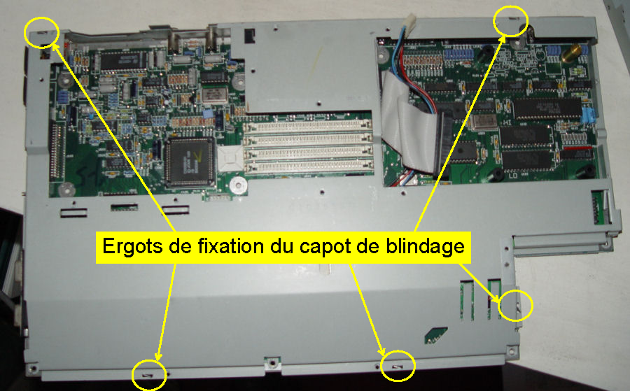 Opening the shield requires to "align" the fixation lugs that hold the shield in place. This has already been explained in the withdrawal of the power supply shield. It consists in aligning the fixation lugs with the slot underneath with a flat pliers. The number and position of lugs vary by model and revisions. The example shown is taken from relatively recent STE. So you have to "go around" the shields and line up all the lugs (if you missed one, you'll know soon)
 And now, you have full access to the motherboard.
For completeness, note that the PCB rests on an insulating plate, which itself rests on the bottom of the metal shield. It may be necessary to remove it to look at some straps underneath the motherboard.
Back to the top
Comple reassembly of the Atari
As indicated earlier in this page just do the revers of the deassembling procedure. Here is a check list:
- Put the insulating plate on the bottom metal shield
- Place the motherboard on the insulating plate
- Put the shield cover back on top of the electronic assembly and replace the fixation lugs.
- Reinstall the power supply and the power connectors
- Place the electronic assembly into the bottom plastic enclosure
- Put back the three screws holding down the assembly and the two screws of the power supply
- Put in place the floppy drive, return the ATARI and put the three screws
- Plug the power connector and the interface connector of the floppy drive
- If you have an Atari STE reinstall the memory modules.
- Before closing the metal shield, perform a quick test of the system. For that matter You just need to connect the power and monitors cables, insert a floppy disk and start the system. The system should boot from the floppy disk but because the keyboard is not connected, there is not much you can do.
- If all works well put back the floppy shield with the two screws.
- Put back the shield of the power supply with the four screws and two finger lugs. Be careful not to forget put the power supply shield into the slots at the bottom.
- Put back the keyboard connector (it is keyed so no problem of putting it the wrong way)
- Place the keyboard in place
- Before closing the Atari , we do another test with a mouse connected. The system must boot from the the floppy disk and we should be able to lunch programs using the mouse and keyboard to make sure that everything works fine.
- If everything works as expected then we can closed the Atari enclosure. When the enclosure is in place, we need to put back the three short screws at the bottom edge and the four longer screws at the top edge
Démontage du disque SH 205 (sorry in French only)
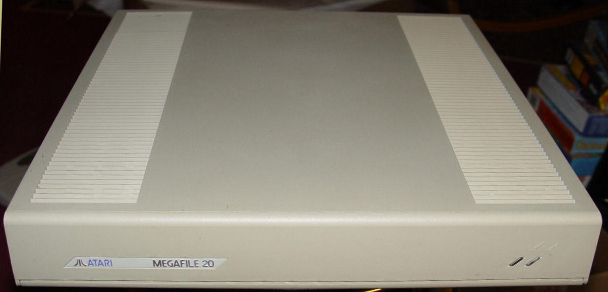 Le disque dur SH 205 également connu sous le nom de Megafile 20 est comme son nom le suggère est disque de 20 Mo ce qui est une taille ridicule de nos jours,
mais qui semblait beaucoup à l'époque.
Le disque dur SH 205 également connu sous le nom de Megafile 20 est comme son nom le suggère est disque de 20 Mo ce qui est une taille ridicule de nos jours,
mais qui semblait beaucoup à l'époque.
Comme pour le démontage de l'ordinateur, je vais décrire les différentes étapes logiques :
- Démontage du capot supérieur
- Démontage du carter métallique
- Démontage des connecteurs du disque
- Démontage du disque
- Démontage de l'alimentation
- Démontage de la plaque électronique.
Démontage du capot supérieur
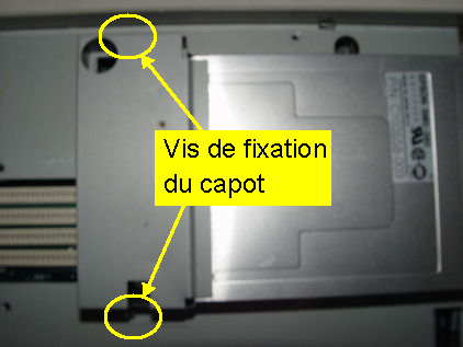
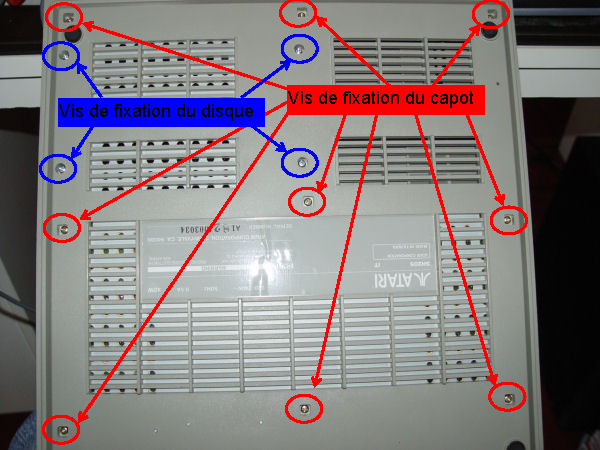 Pour démonter le capot supérieur,
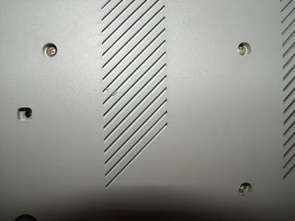
il faut retourner le disque, localisé les 9 vis de fixation et de les dévisser. Attention de n'enlever que les vis de fixation
du capot et non pas les vis de fixation du disque. Une fois cette opération réalisée il est possible d'enlever le capot plastique supérieur.
Pour démonter le capot supérieur,
il faut retourner le disque, localisé les 9 vis de fixation et de les dévisser. Attention de n'enlever que les vis de fixation
du capot et non pas les vis de fixation du disque. Une fois cette opération réalisée il est possible d'enlever le capot plastique supérieur.
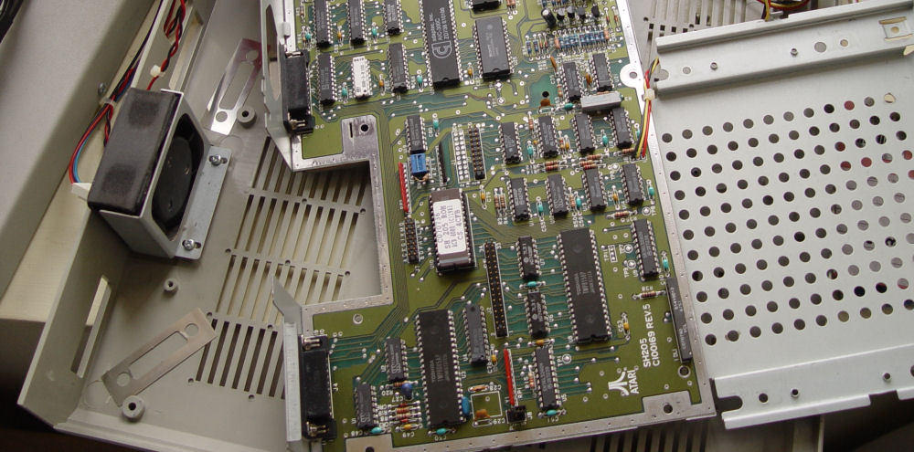
Démontage du carter métallique
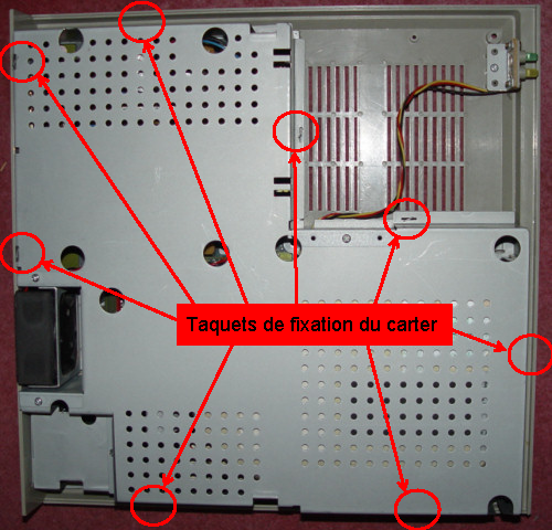
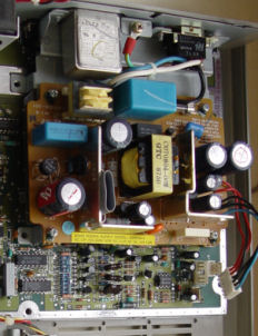
 Comme pour les ordinateurs Atari, toute l'électronique du disque dur est enfermée dans un carter métallique afin de limiter au minimum les émissions RF.
Pour démonter le capot il suffit de "détordre" les ergots de fixation afin de les aligner avec les fentes situées en dessous
comme cela est expliqué dans le démontage du capot de l'Atari. Il y a 8 ergots à dégager.
Comme pour les ordinateurs Atari, toute l'électronique du disque dur est enfermée dans un carter métallique afin de limiter au minimum les émissions RF.
Pour démonter le capot il suffit de "détordre" les ergots de fixation afin de les aligner avec les fentes situées en dessous
comme cela est expliqué dans le démontage du capot de l'Atari. Il y a 8 ergots à dégager.
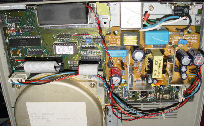
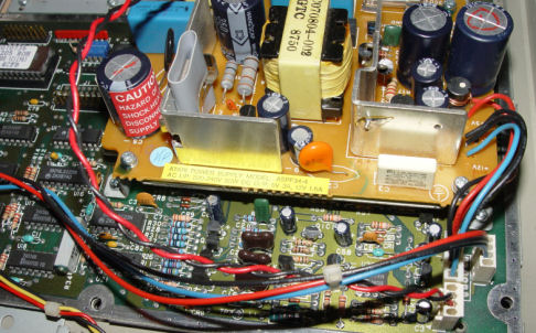
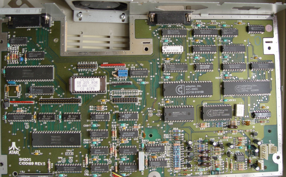
Il est maintenant possible d'enlever le capot et de faire apparaître l'électronique du disque dur.
Back to the topDémontage des connecteurs du disque

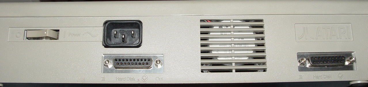
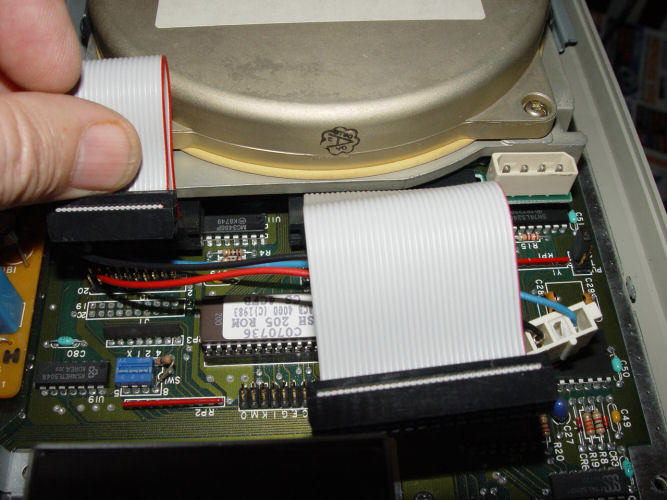 Le disque dur sur le SH205 que j'ai est un disque dur Seagate ST-225, donc un disque dur MFM avec deux connecteurs pour la logique électronique et un
connecteur d'alimentation (il existe des versions en SCSI?). Il n'est pas possible de démonter les connecteurs du côté disque par manque de place et
il faut donc simplement déconnecter les câbles côté plaque électronique ainsi que le connecteur d'alimentation. Pour enlever les connecteurs sans tirer
sur les fils je recommande l'utilisation d'une pince.
Le disque dur sur le SH205 que j'ai est un disque dur Seagate ST-225, donc un disque dur MFM avec deux connecteurs pour la logique électronique et un
connecteur d'alimentation (il existe des versions en SCSI?). Il n'est pas possible de démonter les connecteurs du côté disque par manque de place et
il faut donc simplement déconnecter les câbles côté plaque électronique ainsi que le connecteur d'alimentation. Pour enlever les connecteurs sans tirer
sur les fils je recommande l'utilisation d'une pince.
Démontage du disque
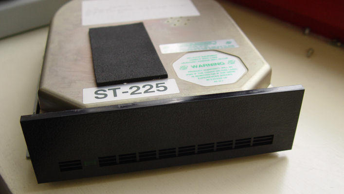
 Il faut à nouveau retourner le boîtier et dévisser les quatre vis restantes du disque. Une fois ces vis enlevées il est
possible de retirer le disque qui est fixé sur des équerres métalliques montées, semble-t-il avec des amortisseurs. Manipulez avec précaution cet
ancêtre, car vous n'avez probablement pas "parqué les têtes" et donc il est plus vulnérable !
Il faut à nouveau retourner le boîtier et dévisser les quatre vis restantes du disque. Une fois ces vis enlevées il est
possible de retirer le disque qui est fixé sur des équerres métalliques montées, semble-t-il avec des amortisseurs. Manipulez avec précaution cet
ancêtre, car vous n'avez probablement pas "parqué les têtes" et donc il est plus vulnérable !
Démontage de l'alimentation
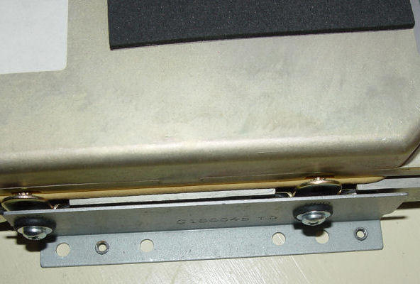
 L'alimentation du SH205 est, semble-t-il, la même que sur les ordinateurs Atari. Il faut commencer par enlever le connecteur qui va vers la plaque
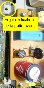
électronique puis par enlever, puis les deux vis à l'arrière de l'alimentation. Pour la sortir il faut la faire basculer vers les deux fixations
avant qui comme vous le savez ont un petit ergot qui rentre dans la plaque électronique afin de garantir le positionnement
correct de celle-ci. De ce fait, il est assez difficile d'enlever l'alimentation qui reste bloquée par ses pattes et il peut être nécessaire d'enlever la plaque
électronique du châssis (comme indique ci-dessous) afin d'avoir un peu plus d'aisance.
L'alimentation du SH205 est, semble-t-il, la même que sur les ordinateurs Atari. Il faut commencer par enlever le connecteur qui va vers la plaque
électronique puis par enlever, puis les deux vis à l'arrière de l'alimentation. Pour la sortir il faut la faire basculer vers les deux fixations
avant qui comme vous le savez ont un petit ergot qui rentre dans la plaque électronique afin de garantir le positionnement
correct de celle-ci. De ce fait, il est assez difficile d'enlever l'alimentation qui reste bloquée par ses pattes et il peut être nécessaire d'enlever la plaque
électronique du châssis (comme indique ci-dessous) afin d'avoir un peu plus d'aisance.
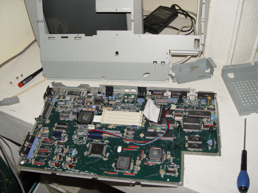
Démontage de la plaque électronique
 Une fois les vis de l'alimentation retirées il ne reste plus qu'une vis à dévisser pour pouvoir enlever le châssis inférieur sur lequel est posée la plaque
électronique. Et voilà votre disque dur est complètement désossé.
Une fois les vis de l'alimentation retirées il ne reste plus qu'une vis à dévisser pour pouvoir enlever le châssis inférieur sur lequel est posée la plaque
électronique. Et voilà votre disque dur est complètement désossé.
Le remontage n'est pas détaillé, car il suffit de faire l'ensemble des opérations décrites ci-dessus dans l'ordre inverse. Comme d'habitude avant de tout refermer je conseille de faire un test.
Back to the top