![]() Version Française de ce document
Version Française de ce document
This page provides various information about the memory of the Atari computers. Some of information comes from my Atari FAQ and it is possible to find additional information on the FAQ about the memory for the falcon and the extension beyond 4Mo.
The following subjects are covered:
- Expanding Memory for SIMM equipped models
- Expending memory for DRAM equipped models
- Information about installed memory and test
Expanding memory for SIMM equipped models
This paragraph gives general information on expanding memory of Atari computers equipped with SIMM modules, the different memory configurations, and some advice on their installation. In order to help in the identification of the memories modules a paragraph is devoted to old memories modules. To install the SIMM memories it is necessary to reach the memory connectors and to remove the existing modules.
Back to the topGeneral Information
The 520/1040 STE Atari's models are equipped with SIMM memory sockets and it is therefore possible to easily increase the capacity of the memory up to 4MB.
Although the information presented here have been validated on Atari STE models it should equally apply to any Atari's models equipped with SIMM connectors (e.g. Mega models). Be also aware that some very early STE models were equipped with SIP modules which are extremely difficult to find and not covered in this presentation.
The Atari STE models have four SIMM memory sockets numbered from 1 to 4 (going from back to front of the system). These sockets are specifically designed to ensure that once inserted, the SIMM will be held in place tightly.
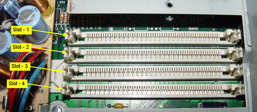
The Atari STE models only accept the SIMM 30 pins / 8 Bits memory modules with or without parity bits and with a capacity of 256KB or 1MB exclusively (i.e. do not try 2MB, 4MB, 8MB, 16MB modules). The minimum speed for SIMM modules is of 150ns for the 256KB and 120ns for the 1MB. It is generally easy, and perfectly appropriate, to find 256KB modules at 120ns and 1MB modules at 100ns or 80ns. For information the fastest SIMM 30 modules are running at 60ns and they use memories are of FPM type (Fast Page asynchronous Mode) which are faster than the normal DRAM. The original SIMM modules used in Atari were not of EDO type but as for parity it should not matter.
It is recommended not to mix SIMMs modules with different speeds on the same machine as it usually does not work reliably. And if you need to buy SIMM modules for your Atari make sure you buy SIMM 30 which should not be confused with the SIMM 72 used in the PCs.
![]() The SIMM 30 modules have a 30 pins connector with gold
or tin/lead contacts, a hole on each side (this is to ensure that the module is well inserted before tilting it), and a notch on the left (this ensure
that the module is not inserted backward). The PCB has 30 pins on each side but the corresponding pins on these two sides
are connected together. The size of the data bus on the SIMM 30 is 8 bits with possibly one 9th bit for parity (not used in Atari). As the
data bus of Atari is 16bits wide that explains why the memories must always be installed in pair.
The SIMM 30 modules have a 30 pins connector with gold
or tin/lead contacts, a hole on each side (this is to ensure that the module is well inserted before tilting it), and a notch on the left (this ensure
that the module is not inserted backward). The PCB has 30 pins on each side but the corresponding pins on these two sides
are connected together. The size of the data bus on the SIMM 30 is 8 bits with possibly one 9th bit for parity (not used in Atari). As the
data bus of Atari is 16bits wide that explains why the memories must always be installed in pair.
The pinout and the names of signals on SIMM 30 are indicated in the table below.
| Pine # | signal name | Signal Description | Pine # | signal name | Signal Description | Pine # | signal name | Signal Description | ||
|---|---|---|---|---|---|---|---|---|---|---|
| 1 | VCC | +5 VDC | 11 | A4 | Address 4 | 21 | /WE | Write Enable | ||
| 2 | /CAS | Column Address Strobe | 12 | A5 | Address 5 | 22 | GND | Ground | ||
| 3 | DQ0 | Data 0 | 13 | DQ3 | Data 3 | 23 | DQ6 | Data 6 | ||
| 4 | A0 | Address 0 | 14 | A6 | Address 6 | 24 | A11 | Address 11 | ||
| 5 | A1 | Address 1 | 15 | A7 | Address 7 | 25 | DQ7 | Data 7 | ||
| 6 | DQ1 | Data 1 | 16 | DQ4 | Data 4 | 26 | QP | Data Parity Out | ||
| 7 | A2 | Address 2 | 17 | A8 | Address 8 | 27 | /RAS | Row Address Strobe | ||
| 8 | A3 | Address 3 | 18 | A9 | Address 9 | 28 | /CASP | Parity CAS | ||
| 9 | GND | Ground | 19 | A10 | Address 10 | 29 | DP | Data Parity In | ||
| 10 | DQ2 | Data 2 | 20 | DQ5 | Data 5 | 30 | VCC | +5 VDC |
Note: QP and DP are NC (non connected) on the SIMM without parity
A9 is NC on 256KB, A10 is NC on 256KB and 1MB. A11 is NC on 256KB, 1MB and 4MB
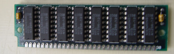
Depending to the age of the modules you will find boards with more or less of circuits (in general from 3 to 8) - see pictures below
 |
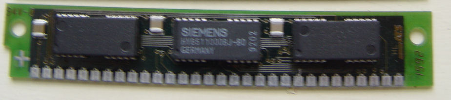 |
It is in general possible to guess the size and the speed of the memory by reading the indications on the circuits used:
 |
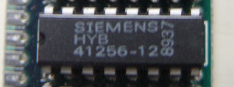 |
On the left a 1MB circuit with 80ns access time on the right a 256KB circuit with 120ns access time
Back to the topMemory Configurations
The original Atari 520STE models are equipped with 2x256KB SIMM modules, and the 1040STE models are equipped with with 4x256KB SIMM modules
The following memory configuration are possible on the STE:
| Total capacity | Boards | Slots | Notes |
| 512KB | 2 x 256KB | 1, 3 | 520STE |
| 1MB | 4 x 256KB | 1, 2, 3, 4 | 1040STE |
| 2MB | 2 x 1MB | 1, 3 | |
| 4MB | 4 x 1MB | 1, 2, 3, 4 |
It is often asked whether it is possible to install 2x256KB with 2x1MB modules (2.5MB configuration). Because of a bug in the TOS this configuration is not correctly recognized. However there are some “bootup” programs such as simmfix and silkboot2e which are supposed to correct this problem. These programs can be found on Internet but they are far from being reliable. As it is increasingly difficult to find 256KB modules it is strongly advice to avoid this configuration. However if you really want to try it follow these instructions
Back to the topMemory Installation
The installation of news memories requires to remove the plastic cover of the computer, as well asto remove the metal-shield that covers the power supply and memory, but it is not necessary to disconnect the keyboard (although it is more practical).
You first have to remove the existing memory. To remove a SIMM module, the two plastic clips at each end must be pulled to the side, then the module must be tilted back and pulled out. It is important to gently release the socket clips one at time. This might be best accomplished with a small flat blade screwdriver. Be aware that is easy to break the clip if too much pressure is applied and that If you break the clips, the SIMM module will not be properly held.
The installation of the memories is extremely simple. You have to insert the SIMM modules (with the notch located on the right i.e. with the memory components located in the back of the board) in the socket at an angle of approximately 45° with the vertical. Once the module is fully engaged at the bottom of the socket you have to tilt it upwards until they are perpendicular to the motherboard. Special plastic clips on both side of the sockets snap in place when the SIMM is in its upright position. Normally it is impossible to install SIMM modules incorrectly, as the notch prevents you to position the module backward and if it is not fully inserted in the socket the holes prevent you to tilt it. It is however necessary to verify that the clips on each side of the module are correctly snapped so that the module is held firmly.
The installation is performed starting from the back socket (slot 1) and by adding the modules progressively. Note that going from a configuration using slots 1 and 3 to a configuration using the four slots requires to remove the memory in slot 3. In other term do not try to install a memory in slot 2 if there is already one in slot 3 as this is not possible.
Back to the topInformation about old memory modules
This short paragraph gives information on SIP, SIMM 30 and SIMM 72 modules.
SIP Modules
 SIP (Single In-Line Package) modules are
presented in the form of a board with 30 pins to insert in a receiving connector. These modules have either a capacity of 256 KB, or of 1 MB. Its 30 pins often
bent or broke during installation. It has been reported that the SIP modules
have been used in early STE models (preproduction?).
SIP (Single In-Line Package) modules are
presented in the form of a board with 30 pins to insert in a receiving connector. These modules have either a capacity of 256 KB, or of 1 MB. Its 30 pins often
bent or broke during installation. It has been reported that the SIP modules
have been used in early STE models (preproduction?).
SIMM 30 pins / 8bits
 8 bits as SIMM (Single In-Line Memory Module) modules (often referred as
SIMM 30) are PCB of approximately 8.5 cm in length, on which electronic components are installed (always on only one side of the board). Modules are always
installed in group of two often called bank. These modules can have a capacity of 256 KB, 1 MB or 4 MB (later 8MB and 16MB were built). Each module has a
notch in the left lower corner which is used as a locating pin, thus avoiding to insert backward. The SIMM 30 are the modules to be used on the Atari
STE models.
8 bits as SIMM (Single In-Line Memory Module) modules (often referred as
SIMM 30) are PCB of approximately 8.5 cm in length, on which electronic components are installed (always on only one side of the board). Modules are always
installed in group of two often called bank. These modules can have a capacity of 256 KB, 1 MB or 4 MB (later 8MB and 16MB were built). Each module has a
notch in the left lower corner which is used as a locating pin, thus avoiding to insert backward. The SIMM 30 are the modules to be used on the Atari
STE models.
SIMM 72 pins / 32bits
 32 bits SIMM modules (often referred as
SIMM 72) are PCB of approximately 10.5 cm in length on which electronic components are installed (often on both side of the board).
The SIMM 72 modules are available in 1 MB, 2 MB, 4 MB, 8 MB, 16 MB, 32 MB and 64 MB. These modules are especially used with 486 or Pentium PC motherboards. SIMM
72 modules have two notches, a notch in the left lower corner (like the SIMM 30) plus a round notch located in the center of the bar. The SIMM
72 connector has 72 pins on each side, but corresponding pins are connected together. The SIMM 72 modules are not usable for Atari.
32 bits SIMM modules (often referred as
SIMM 72) are PCB of approximately 10.5 cm in length on which electronic components are installed (often on both side of the board).
The SIMM 72 modules are available in 1 MB, 2 MB, 4 MB, 8 MB, 16 MB, 32 MB and 64 MB. These modules are especially used with 486 or Pentium PC motherboards. SIMM
72 modules have two notches, a notch in the left lower corner (like the SIMM 30) plus a round notch located in the center of the bar. The SIMM
72 connector has 72 pins on each side, but corresponding pins are connected together. The SIMM 72 modules are not usable for Atari.
Expanding memories for DRAM equipped models
Certain models of Atari (in particular 520/1040 STF) are equipped with DRAM circuits which are directly soldered onto the motherboard of the computer. This makes the addition of memory extremely difficult.
Usage of special memory upgrade board
One way of increasing the memory size while limiting the soldering operations is to use a special memory upgrade board which replaces the original banks of memories with SIMM modules installed directly on this upgrade board. It is then possible to upgrade an STF model to a configuration with 1MB, 2MB, or 4MB. Considering the complexity of the operation, the majority of these modules are equipped with 4MB. There were several solutions available like the Marpet Xtra Ram board, the Aixit 10Mb expansion board, or the JRI-RAM+ board. But it is probably extremely difficult to find these boards nowadays.
Back to the topExample of the JRI-RAM+ upgrade board
As an example, I provide some details about an Atari 520 STF equipped with one of these upgrade kit. This upgrade kit is composed of two boards developed by “John Russel innovations (Pittsburg CA) and is called the JRI-RAM+. Some more technical information ca be found on this document. This board was installed by B&C Computer (one of the most famous Atari stores in Bay area), because the installation, as you will see, is rather delicate. The main board which receives the SIMM modules must be connected to the power lines (this is the only simple thing), to the data bus, to the address bus, and to several control signals. For that matter, a certain number of individual wires (control signals) are soldered directly on the motherboard. Then, a first bus is connected to the board by soldering a “connector" directly onto one of the original DRAM (see detail picture below). And finally the original Shifter circuit (C025914-38A), which is located in a shielded trap, is removed and replaced by a small board containing 2 Shifter circuits (this provide a 4096 colors pallet to your Atari) and a bus cable that goes to the main memory upgrade board.
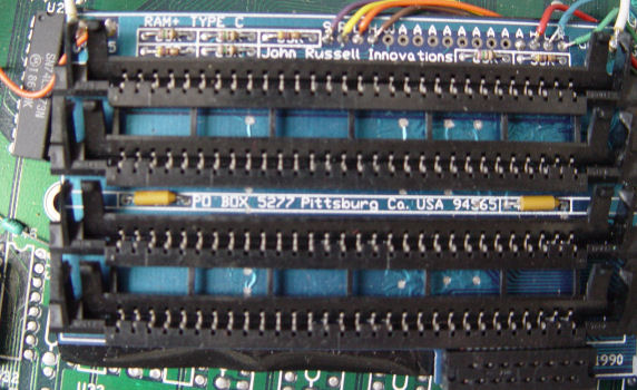 |
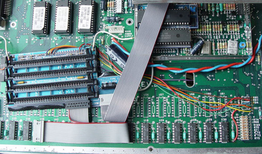 |
| Main JRI - RAM+ board | All the connections to the JRI-RAM+ boards |
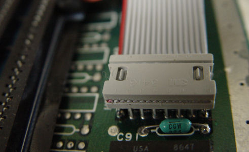 |
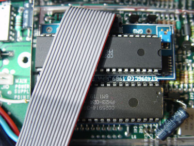 |
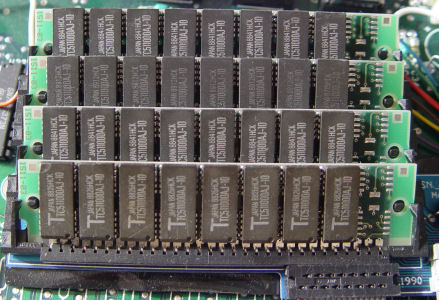 |
| Detail of the connection on a DRAM | Small board located on the Shifter socket | SIMM modules installed |
The complete upgrade in place with the shifter shield trap half-closed.
Back to the topDIY Installation of memory
The DIY installation requires a solid electronic knowledge (and access to the schematics of your Atari) and good soldering skill and is surely not recommended
the faint hearted!
Some description of these modifications can be found in the following documents:
- Instruction in German (but with diagrams interesting)
- Instruction in English
Special case of the 520STF
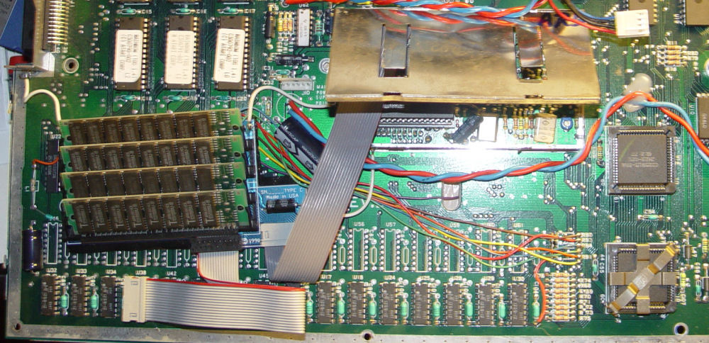
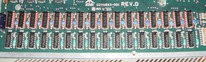
You have to know that that for the same Atari model there have been multiple revision of the motherboards PCB. The general tendency has been that the early versions of the PCB had more components than the following versions (tendency to integrate several components in one chip), that many components were installed on support, and… of course the board had much more straps! Therefore some early models of 520STF were equipped with 512KB memory directly soldered on the motherboard, but they also had 16 extra sockets to add DRAM. Thus in this particular case it is extremely simple to add the DRAM components in the sockets to upgrade your atari to 1MB. The only problem is that the required 256Kbits NMOS DRAM with access times of 150ns or less are difficult to find. Example of such DRAM are MT1259-12 (Tecnology Micron), MB81256-15 (Fujitsu), etc… In case the socket are not originally installed of it is still possible to do it, but this is not simple, because the PCB holes are usually filled with solder and it is necessary to empty each of the holes of the supports and you should also add one decoupling capacitor for each DRAM. An example is shown below (note that the original DRAM are 150ns and added one on socket are 120ns)
There is also this procedure to add memory to a STF described by Christopher Hicks. The only doubt that I have is that the final configuration is 2,5 Mo which, due to a bug of the TOS, does not work?
Back to the topInformation about installed memory and tests
How do I to know how much memory is installed on my machine and how do I to know if it works correctly?
Unfortunately the TOS from Atari does not give any indication on the memory installed and it is thus necessary to use a special program to know about your configuration. There is an excellent program which gives lots of information on the system and in particular on the memory installed. There is also an accessory which gives the size of the remaining memory.
In finally this program test the memory installed.
Back to the top