This page contains information about ST Floppy disks from a software "point of view": This includes information on FD layouts, Low and High level FD format, FD images, etc...
There is another page on the Hardware side of the Atari ST Floppy Disks containing information on the Floppy Disk Media (down to the flux level), the FD Drives, the FD controller, etc ...
This information should be specially usefull for duplication (backup) or preservation (images) of Atari ST diskettes (protected or not).
Atari Low Level Formatting
The first step in preparing a diskette involves the creation of the actual structures on the surface of the media that are used to hold the data. This means recording the tracks and marking the start of each sector on each track. This is called low-level formatting, and sometimes it is called "true formatting" since it is actually recording the format that will be used to store information on the disk. Once the floppy disk has been low-level formatted, the locations of the tracks and sectors on the disk are fixed in place.
- Atari / PC / ISO DD Formats
- Atari Standard Double Density Format
- Standard 9-10-11 Sectors of 512 Bytes Format
- Standards 128-256-512-1024 Bytes / Sector Format
Atari / PC / ISO Formats
The Atari ST uses the Western Digital WD1772 Floppy Disc Controller (FDC) to
access the 3 1/2 inch (or to be more precise 90mm) floppy disks. Western Digital was recommending to use the IBM 3740 Format for Single Density diskette and to use the
IBM System 34 Format for Double Density diskette. Actually the default Atari Format used by the TOS is
slightly different (nearer to the ISO Double Density Format) as it does not have an IAM byte (and associated GAP),
before the first IDAM sector of the track (see diagram below).
However the WD1772 ( and therefore the Atari) is capable to read both format without problem but the reverse is usually not true (i.e. floppies formatted on
early Atari machines can't be read on PCs but floppies created on PC can be read on Atari).
 IBM System 34 Double Density Format (this is the format produced on a DOS machine formatting in 720K)
 ISO Double Density Format.
Atari Standard Double Density Format
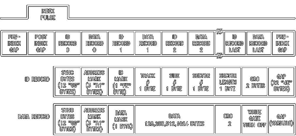
Below is a detail description of the "Standard Atari Double Density Format" as created by the early TOS.
Note: There is no standard GAPS naming convention and it is not clear on how they must be decomposed. This document uses a GAP naming/numbering scheme which is a combination of the IBM and ISO standards with more
details for the description of the GAP between the ID record and the DATA record. Usually only one gap is used to describe the content between these two records but here we decompose it into a post
ID gap (Gap 3a) and a pre-data gap (Gap 3b) as this allow a more detail description. Of course they can be easily combined into one Gap 3 which is more conventional. Not show
in the diagram below when the floppy is formatted with an IAM (index address mark) the Gap1 is further decomposed into two gaps: A post index gap (Gap1a) and a post
IAM gap (Gap1b).
The tables below indicates the standard values of the different gaps in a "standard" Atari diskette with 9 sectors of 512 user data bytes. It also indicates the minimum acceptable values of these gaps, as specified in the WD1772 datasheet, when formatting non standard diskettes.
| Name | Standard Values (9 sectors) | Minimum Values (Datasheet) |
| Gap 1 Post Index | 60 x $4E | 32 x $4E |
| Gap 2 Pre ID | 12 x $00 + 3 x $A1 | 8 x 00 + 3 x $A1 |
| Gap 3a Post ID | 22 x $4E | 22 x $4E |
| Gap 3b Pre Data | 12 x $00 + 3 x $A1 | 12 x $00 + 3 x $A1 |
| Gap 4 Post Data | 40 x $4E | 24 x $4E |
| Gap 5 Pre Index | ~ 664 x $4E | 16 x $4E |
Standard Record Gap Value (Gap 2 + Gap 3a + Gap 3b + Gap 4) = 92 Bytes / Record
Minimum Record Gap Value (Gap 2 + Gap 3a + Gap 3b + Gap 4) = 72 Bytes / Record
Standard Record Length (Record Gap + ID + DATA) = 92 + 7 + 515 = 614 bytes
Minimum Record Length (Record GAP + ID + DATA) = 72 + 7 + 515 = 594
Standard 9-10-11 Sectors of 512 Bytes Format
Note that the 3 1/2 FD are spinning at 300 RPM which implies a 200 ms total track time. As the MFM cells have a length of 4 µsec this gives a total of 50000 cells and therefore about 6250 bytes per track.
The table below indicates possible (i.e. classical) values of the gaps for tracks with 9, 10, and 11 sectors.
| Name | 9 Sectors: # bytes | 10 Sectors: # bytes | 11 Sectors: # bytes |
| Gap 1 Post Index | 60 x $4E | 60 x $4E | 10 x $4E |
| Gap 2 Pre ID | 12 x $00 + 3 x $A1 | 12 x $00 + 3 x $A1 | 3 x $00 + 3 x $A1 |
| Gap 3a Post ID | 22 x $4E | 22 x $4E | 22 x $4E |
| Gap 3b Pre Data | 12 x $00 + 3 x $A1 | 12 x $00 + 3 x $A1 | 12 x $00 + 3 x $A1 |
| Gap 4 Post Data | 40 x $4E | 40 x $4E | 1 x $4E |
| Gap 2-4 (bytes) | 92 | 92 | 44 |
| Record Length (bytes) | 614 | 614 | 566 |
| Gap 5 Pre Index (bytes) | 664 | 50 | 20 |
| Total Track (bytes) | 6250 | 6250 | 6250 |
Respecting all the minimum value on an 11 sectors / track gives a length of: L = Min Gap 1 + (11 x Min Record Length) + Min Gap 5 = 32 + 6534 + 16 = 6582 (which is 332 bytes above max track length). Therefore we need to decrease by about 32 bytes per sector in order to be able to write such a track. For example the last column of the table above shows values as used by Superformat v2.2 program for 11 sectors/track (values analyzed with a Discovery Cartridge). As you can see the track is formatted with a Gap 2 reduced to 6 and Gap 4 reduced to 1 !
These values do not
respect the minimum specified by the WD1772 datasheet but they make sense as it is mandatory to let enough time to the FDC between the ID block and the
corresponding DATA block which implies that Gap 3a & 3b should not be shorten. The reduction of gap 4 plus gap 2
to only 7 bytes between a DATA block and the next ID block does not let enough time to the FDC to read the next sector on the fly but
this is acceptable as this sector can be read on the next rotation of the FD. This has an obviously impact on performance that can be minimized by using
sectors interleaving (explain below). But it is somewhat dangerous to have
such a short gap between the data and the next ID because the writing of a data block need to be perfectly calibrated or it will collide with
the next ID block. This is why such a track is actually reported as "read only" in
the DC documentation and is sometimes used as a protection mechanism.
Of course you have more chance to successfully write 11 sectors on the first track (the outer one) than on the last track (the inner one) as the bit
density gets higher in the later case. It is also important to have a floppy drive that have a stable and minimum rotation speed deviation (i.e.
RPM should not be more than 1% above 300).
Standard 128-256-512-1024 Bytes / Sector Format
The table below indicates some "classical" gaps values for tracks with sectors of size of 128, 256, 512, and 1024.
| Name | 29 sectors of 128 bytes | 18 sectors of 256 bytes | 9 Sectors of 512 bytes | 5 Sectors of 1024 bytes |
| Gap 1 Post Index | 40 | 42 | 60 | 60 |
| Gap 2 Pre ID | 10+3 | 11+3 | 12+3 | 40+3 |
| Gap 3a Post ID | 22 | 22 | 22 | 22 |
| Gap 3b Pre Data | 12+3 | 12+3 | 12+3 | 12+3 |
| Gap 4 Post Data | 25 | 26 | 40 | 40 |
| Gap 2-4 | 75 | 77 | 92 | 120 |
| Record Length | 213 | 343 | 614 | 1154 |
| Gap 5 | 73 | 76 | 664 | 480 |
| Total Track | 6250 | 6250 | 6250 | 6250 |
Interleaving: Normally the sector number is incremented by 1 for each record (i.e. there is no need to interleave with DD like it used to be with older FD) however sectors can written be in any order.
Overall Track / Sector Description
Track Description
Sector ID Segment
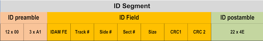
- ID PREAMBLE
- PLL SYNCH FIELD
This is a 12 bytes long field of repetitive clocked data bits. The preamble normally will be all zeroes of NRZ data (encoded as 1010. . . in MFM). During the ID preamble, the signal Read Gate will go active, indicating that the incoming data pattern has to be locked on to. - ID SYNCH FIELD
The synch mark byte contains a missing clock code violation, typically in MFM. The violation is detected by circuitry to indicate the start of an ID Field or a Data Field. The first decoded byte that does not contain all 0s after the preamble will be the synch mark. The first 1 to be received is then used to byte align after the all zeroes preamble. The DD format have three ID synch mark byte. On soft sectored drives Synch field precedes the address mark (AM).
- PLL SYNCH FIELD
- ID FIELD
- ID ADDRESS MARK FIELD
ID Address Mark (IDAM) is required on soft sectored drives to indicate the beginning of a sector, because this type of drive does not have a sector pulse at the start of each sector. - ID content Field
The ID content Field format contains a track number bytes, a sector number byte, a head number byte. It is 4 bytes long. - ID CRC FIELD
CRC (Cyclic Redundancy Checking) code is appended to the header field. The CRC consists of two bytes of the standard CRC-CCITT polynomial. The code detects errors in the header field. This appendage is basically a protection field to make sure that the ID field contains valid information.
- ID ADDRESS MARK FIELD
- ID POSTAMBLE
This field is used to give the disk controller time to interpret the data found in the ID field and to act upon it. It provides slack for write splicing that occurs between the ID and Data segment. A Write splice occurs when the read/ write head starts writing the data field. A splice is created each time a sector's data segment is written to. The slight variations in the rotational speeds cause the first flux change to occur in different positions for each write operation. It also allows time in a write disk operation for the read/write circuitry to be switched from read to write mode. Finally it allows time for the PLL circuit to re-lock on to a fixed reference clock before it returns to synchronize to the preamble of the data field.
Sector DATA Segment
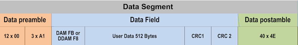
- Data PREAMBLE FIELD
- PLL Synch Field
The Data Preamble field is necessary when reading a sector's data. It ensures that the PLL circuit locks on to the Data segment data rate. Initially, the ID segment and the data segment of every sector will be written when formatting the disk, but the Data segment will be written over later. Due to drive motor speed variations within the tolerance specified, the ID and Data segments will have slightly different data rates because they are written at different times. This implies that the PLL must adjust its frequency and phase in order to lock on to the data rate of the Data segment before the incoming preamble field has finished. Hence the need for a second preamble field in the sector. - DATA SYNCH FIELD
Following the PLL Synch Field will be the Data synch field similar to the ID synch field.
- PLL Synch Field
- DATA FIELD
- Data Address Mark field
Following the Data Preamble will be the Data Address Mark for soft sectored drives similar to the ID Address Mark field. - Data Content Field
The Data field is transferred to or from external memory. It is usually from 128 bytes to 1024 bytes per sector. - DATA CRC
A CRC appendage follows the Data field. CRC generating (when writing to the disk) and checking (when reading from the disk) are performed on the Data field. Errors may therefore be detected.
- Data Address Mark field
- DATA POSTAMBLE FIELD
This has the same function as the ID Postamble field. It is the final field of the sector. It allows slack between neighboring sectors. Without this gap, whenever a data segment is written to a sector, any reduction in drive motor speed at the instance of writing to the disk would cause an overlap of the data segment and the succeeding ID segment of the next sector. This field is only written when formatting the disk.
Note 1: A final gap field is added from the end of the last sector until the INDEX pulse occurs and this gap is often termed Gap 5. It takes up the slack from the end of the last sector to the Index pulse.
Note 2: When writing a sector the write gate is tunrned on at the begining of the DATA preamble (location of the write splicing) and is turned off in the data postamble (one or two bytes after the last CRC).
Back to the topSector Write Splice
The area at the begining of the DATA preamble provides slack for write splicing that occurs between the ID and Data segment. A Write splice occurs when the read/ write head starts writing the data field. A splice is created each time a sector's data segment is written to. The slight variations in the rotational speeds cause the first flux change to occur in different positions for each write operation. It also allows time in a write disk operation for the read/write circuitry to be switched from read to write mode.
Back to the topTrack Write Splice
A Track write splice occurs when writing a complete track. When you write a whole track, you start writing bytes at the index mark for 200ms. The problem is that floppy drives do not run exactly at 300 rpm all the time, so there's pretty much no chance you'll get an exact joining once you've done a complete revolution. So you'll either have some leftover noise just before your starting point, or some overwriting there.
Back to the topAtari High-Level Formating
Getting a floppy disk ready
There are two steps involved in getting a floppy disks ready for usage on an Atari:
- As already described in this section the first step involves the creation of the actual structures on the surface of the media that are used to hold the data ans is called the Low_Level formatting.
- The second step is called the high-level formatting. This is the process of creating the disk's logical structures such as the file allocation table and root directory. The high-level format uses the structures created by the low-level format to prepare the disk to hold files using the chosen file system. In order for the TOS to use a diskette it has to know about the number of tracks, the number of sectors per tracks, the size of the sectors and the number of sides. This information is defined in a special sector called the boot sector. Beyond that it is necessary for the TOS to find information (e.g. location of all the sectors belonging to this file, attributes, ...) about any files stored on the diskette as well as global information (e.g. the space still available on the diskette). This information is kept in directories and FATs structures.
The Boot Sector (BS)
The boot sector is always located on track 0, side 0, first sector of the diskette. This sector is tested by the TOS as soon as you change of diskette to find important information about the diskette (e.g. it contains a serial number that identify the diskette). Some parameters are loaded from this sector to be used by the BIOS and are stored in a structure called the BPB (Bios Parameter Block). Eventually the boot sector also contain a bootstrap routine (the loader) that allow to start a relocatable program a boot time (usually a TOS image).
The structure of the boot sector is described below (the grayed areas are stored in the BPB). Note that the Atari boot sector is similar with the boot sector used by IBM PC and therefore 16 bits words are stored using the low/high bytes Intel format (e.g. a BPS = $00 $02 indicates a $200 bytes per sector).
| Name | Offset | Bytes | Contents |
|---|---|---|---|
| BRA | $00 | 2 | This word contains a 680x0 BRA.S instruction to the bootstrap code in this sector if the disk is executable, otherwise it is unused. |
| OEM | $02 | 6 | These six bytes are reserved for use as any necessary filler information. The disk-based TOS loader program places the string 'Loader' here. |
| SERIAL | $08 | 4 | The low 24-bits of this long represent a unique disk serial number. |
| BPS | $0B | 2 | This is an Intel format word (low byte first) which indicates the number of bytes per sector on the disk (usually 512). |
| SPC | $0D | 1 | This is a byte which indicates the number of sectors per cluster on the disk. Must be a power of 2 (usually 2) |
| RESSEC | $0E | 2 | This is an Intel format word which indicates the number of reserved sectors at the beginning of the media preceding the start of the first FAT, including the boot sector itself. It is usually one for floppies. |
| NFATS | $10 | 1 | This is a byte indicating the number of File Allocation Table's (FAT's) stored on the disk. Usually the value is two as one extra copy of the FAT is kept to recover data if the first FAT gets corrupted. |
| NDIRS | $11 | 2 | This is an Intel format word indicating the total number of file name entries that can be stored in the root directory of the volume. |
| NSECTS | $13 | 2 | This is an Intel format word indicating the number of sectors on the disk (including those reserved). |
| MEDIA | $15 | 1 | This byte is the media descriptor. For hard disks this value is set to 0xF8, otherwise it is unused on Atari. |
| SPF | $16 | 2 | This is an Intel format word indicating the number of sectors occupied by each of the FATs on the volume. Given this information, together with the number of FATs and reserved sectors listed above, we can compute where the root directory begins. Given the number of entries in the root directory, we can also compute where the user data area of the disk begins. |
| SPT | $18 | 2 | This is an Intel format word indicating the number of sectors per track (usually 9) |
| NHEADS | $1A | 2 | This is an Intel format word indicating the number of heads on the disk. For a single side diskette the value is 1 and for a double sided diskette the value is 2. |
| NHID | $1C | 2 | This is an Intel format word indicating the number of hidden sectors on a disk (not used by Atari). |
| EXECFLAG | $1E | 2 | This is a word which is loaded in the cmdload system variable. This flag is used to find out if the command.prg program has to be started after loading the OS. |
| LDMODE | $20 | 2 | This is a word indicating the load mode. If this flag equal zero the file specified by the FNAME field is located and loaded (usually the file is TOS.IMG). If the flag is not equal to zero the sectors as specified by SECTCNT and SSSECT variables are loaded. |
| SSECT | $22 | 2 | This is an Intel format word indicating the logical sector from where we boot. This variable is only used if LDMODE is not equal to zero |
| SECTCNT | $24 | 2 | This is an Intel format word indicating the number of sectors to load for the boot. This variable is only used if LDMODE is not equal to zero |
| LDAADDR | $26 | 2 | This is an Intel format word indicating the memory address where the boot program will be loaded. |
| FATBUF | $2A | 2 | This is an Intel format word indicating the address where the FAT and catalog sectors must be loaded |
| FNAME | $2E | 11 | This is the name of an image file that must be loaded when LDMODE equal zero. It has exactly the same structure as a normal file name, that is 8 characters for the name and 3 characters for the extension. |
| RESERVED | $39 | 2 | Reserved |
| BOOTIT | $3A | 452 | Boot program that can eventually be loaded after loading of the boot sector. |
| CHECKSUM | $1FE | 2 | The entire boot sector word summed with this Motorola format word will equal 0x1234 if the boot sector is executable or some other value if not. |
The data beginning at offset $1E (colored in yellow) are only used for a bootable diskette. To recognize that a diskette is bootable the boot sector must contain the text "Loader" starting at the third bytes and the sum of the entire boot sector should be equal to $1234.
The boot process is usually done in 4 stages:
- The boot sector is loaded and the boot program contained is executed.
- The FAT and the catalog are loaded from the diskette and the loader search for the file name indicated
- The program image is loaded usually starting with address $40000
- The loaded program is executed from the beginning.
See also some Boot sector code.
Directory Structure
The TOS arranges and stores file-system contents in directories. Every file system has at least one directory, called the root directory (also
referred as the catalog in Atari), and may have additional directories either in the root directory or ordered hierarchically below it. The contents
of each directory are described in individual directory entries. The TOS strictly controls the format and content of directories.
The root directory is always the topmost directory. The TOS creates the root directory when it formats the storage medium (
high level formatting). The root directory can hold information for only a fixed number
of files or other directories, and the number cannot be changed without reformatting the medium. A program can identify this limit by examining
the NDIRS field in the BPB structure described in the boot sector section. This field specifies the maximum
number of root-directory entries for the medium.
A user or a program program can add new directories within the current directory, or within other directories. Unlike the root directory, the new
directory is limited only by the amount of space available on the medium, not by a fixed number of entries. The TOS initially allocates only a
single cluster for the directory, allocating additional clusters only when they are needed. Every directory except the root directory has two
entries when it is created. The first entry specifies the directory itself, and the second entry specifies its parent directory—the directory that
contains it. These entries use the special directory names ". "(an ASCII period) and ".." (two ASCII periods), respectively.
The TOS gives programs access to files in the file system. Programs can read from and write to existing files, as well as create new ones. Files can contain any amount of data, up to the limits of the storage medium. Apart from its contents, every file has a name (possibly with an extension), access attributes, and an associated date and time. This information is stored in the file's directory entry, not in the file itself.
The root directory is located just after the FATs (i.e. on a single sided FD: side 0, track 1, sector 3 and on DS DF side 1, track 0, sector 3) and is composed of 7 sectors. Each entry in the root directory can be describe by the following structure:
| Name | Bytes | Contents |
|---|---|---|
| FNAME | 8 | Specifies the name of the file or directory. If the file or directory was created by using a name with
fewer than eight characters, space characters (ASCII $20) fill the remaining bytes in the field. The first byte in the field can be a
character or one of the following values:
|
| FEXT | 3 | Specifies the file or directory extension. If the extension has fewer than three characters, space characters (ASCII $20) fill the remaining bytes in this field. |
| ATTRIB | 1 | Specifies the attributes of
the file or directory. This field can contain some combination of the
following values:
|
| RES | 10 | Reserved; do not use. |
| FTIME | 2 | Specifies the time the file or
directory was created or last updated. The field has the following form:
|
| FDATE | 2 | Specifies the date the file or
directory was created or last updated. The field has the following form:
|
| SCLUSTER | 2 | Specifies the starting cluster of the file or directory (index into the FAT) |
| FSIZE | 4 | Specifies the maximum size of the file, in bytes. |
FAT Structure
The file allocation table (FAT) is an array used by the TOS to keep track of which clusters on a drive have been allocated for each file or directory. As a program creates a new file or adds to an existing one, the system allocates sectors for that file, writes the data to the given sectors, and keeps track of the allocated sectors by recording them in the FAT. To conserve space and speed up record-keeping, each record in the FAT corresponds to two or more consecutive sectors (called a cluster). The number of sectors in a cluster depends on the type and capacity of the drive but is always a power of 2. Every logical drive has at least one FAT, and most drives have two, one serving as a backup should the other fail. The FAT immediately follows the boot sector and any other reserved sectors.
Depending on the number of clusters on the drive, the FAT consists of an array of either 12-bit or 16-bit entries. Drives with more than 4086 clusters have a 16-bit FAT; those with 4086 or fewer clusters have a 12-bit FAT. As Atari diskette has always less than 4086 clusters the FATson Atari diskettes are always 12-bit FATs.
The first two entries in a FAT (3 bytes for a 12-bit FAT) are reserved. In most cases the first byte contains the media descriptor (usually $F9F) and the additional reserved bytes are set to $FFF. Each FAT entry represents a corresponding cluster on the drive. If the cluster is part of a file or directory, the entry contains either a marker specifying the cluster as the last in that file or directory, or an index pointing to the next cluster in the file or directory. If a cluster is not part of a file or directory, the entry contains a value indicating the cluster's status.
The following table shows possible FAT entry values:
| Value | Meaning |
|---|---|
| $000 | Available cluster. |
| $002-$FEF | Index of entry for the next cluster in the file or directory. Note that $001 does not appear in a FAT, since that value corresponds to the FAT's second reserved entry. Index numbering is based on the beginning of the FAT |
| $FF0-$FF6 | Reserved |
| $FF7 | Bad sector in cluster; do not use cluster. |
| $FF8-$FFF | Last cluster of file or directory. (usually the value $FFF is used) |
Each file and directory consists of one or more clusters, each cluster represented by a single entry in the FAT. The SCLUSTER field in the directories structure corresponding to the file or directory specifies the index of the first FAT entry for the file or directory. This entry contains $FFF if there are no further FAT entries for that file or directory, or it contains the index of the next FAT entry for the file or directory. For example, the following segment of a 12-bit FAT shows the FAT entries for a file consisting of four clusters:
- $003 Cluster 2 points to cluster 3
- $005 Cluster 3 points to cluster 5
- $FF7 Cluster 4 contains a bad sector
- $006 Cluster 5 points to cluster 6
- $FFF Cluster 6 is the last cluster for the file
- $000 Clusters 7 is available
- ...
Note that if a cluster contains $000 it does not mean that it is empty but that it is available. This is due to the fact that when a file is deleted the data are not erased but only the first letter of the name of the file in the directory structure is set to $E5 and all clusters used by the deleted file are set to $000.