- Atari Video Presentation
- Atari STE Video Schematic
- Connecting Modern LCD/CRT to an Atari
- Creating Composite Sync Signal on an Atari STFM
- Creating S-video Signals on an Atari STFM
- Atari STFM Composite Video Signal Description
- Basic Video Information
- References
Atari Video Presentation
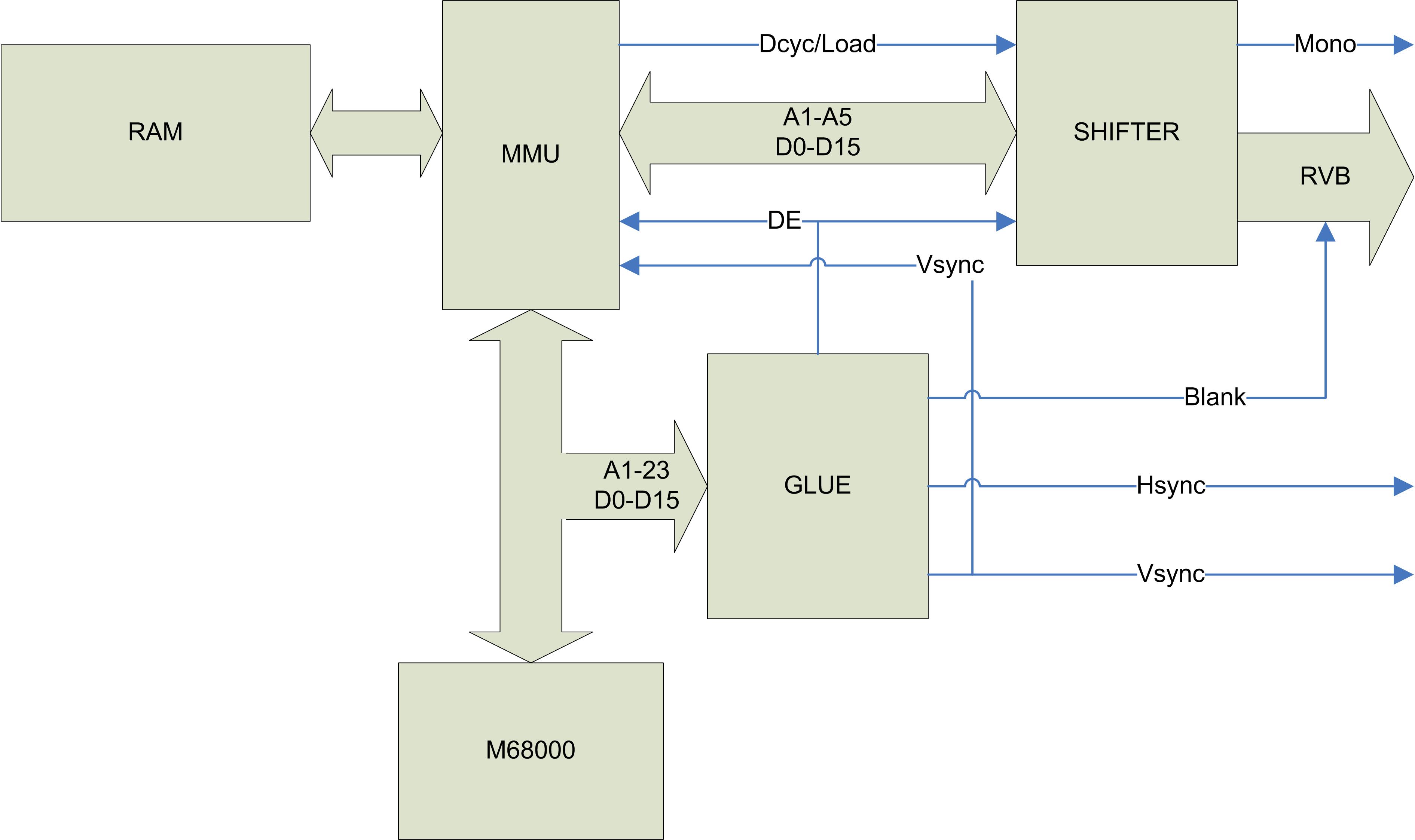
On the right is a high level diagram of the Atari Video circuitry. The associated timings are here
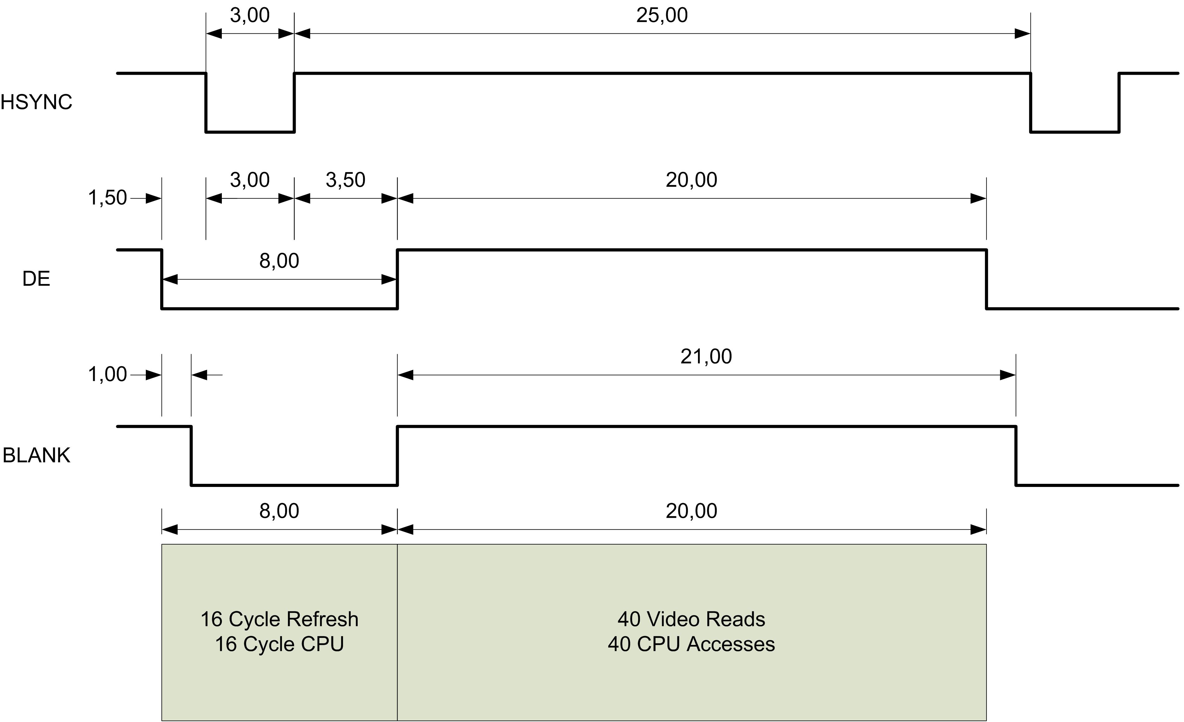
 The Atari video outputs are connected mainly to the Video shifter circuitry as shown on this block diagram. Audio out and in are coming from the Yamaha YM-2149 sound circuit, and the synchronization signals are coming from the Atari Glue chip.
The color outputs on pin 6 (Green), 7 (Red), and 10 (Blue) pass through an amplifier followed by a dump resistor of 27 Ohm resistors on the STF and 75 Ohms resistors on the STE.
The output pin 2 of the video connector depends on the Atari (schematic):
- For an Atari without RF modulator the output on pin 2 is a Composite Sync that only combines the Vsync and Hsync signals, and
- For an Atari with an RF modulator the output on pin 2 is a Composite Video signal.
Pin 8 is connected to 12V / 10mA pins on "recent" ST. However on 520STF this pin is actually connected to GND.
Pin 5 accept an optional audio input signal that can be mixed with the internally generated signal before going to the audio out on pin 1.
Output pin 3 is a programmable TTL output connected to sound chip YM-2149.
Pin 4 is connected the MFP68901 circuit and is used to set the Atari in Hi-resolution when grounded and to Med/Low-resolution when left open. A transition on this pin generates a reset of the system.
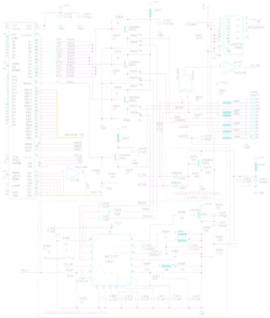
Back to the topAtari STE Video Schematic
The following schematic describe most of the Atari STE video circuitry. The schematic for an Atari Mega STE is very close to this one but the locations of the components are different. However note that the video schematic for an Atari STF is quite different. This is due mainly because of the usage of a totally different version of the Shifter.
Note the presence of two sections which are stuffed or not depending if the Atari is equipped with an RF modulator or not.
The components values indicated on the schematic are for the NTSC version.
Connecting Modern LCD/CRT Monitors to an Atari
There are several problems when trying to connect an Atari to a modern LCD/CRT monitor: The output voltages used are not standard, and the frequencies in Low/Medium color resolution are beyond the capability of most of the recent monitors.
- Atari ST Video Signals
- Connecting an Atari with RF Modulator
- Connection to an Atari without RF Modulator
Atari ST Video Signals Characteristics
The Characteristics of the Video Signals used by the Atari are the following:
- Output Level 1 Volt Peak to Peak (P-P) for Video (R.G.B.) and Synchronization lines
- Horizontal /Vertical Synchronization frequencies:
- 15.75 kHz Horizontal, 50/60 Hz Vertical for Color display,
- 35.7 kHz Horizontal, 71.2Hz Vertical for Monochrome display.
If you can find an old "multisync" monitor like the NEC 14" CRT Multisync II -- built in 1988 it accepts a horizontal frequency in range 15.5-35 kHz and a vertical frequency in range 50-80 Hz and therefore it can directly displays the 3 resolutions of the Atari.
Unfortunately modern "VGA monitors" do not support directly all the resolution of the Atari. While in most case they should work with the Atari in monochrome mode (high resolution), they will probably not work for the color mode (medium-low resolutions) due to the fact that their minimal Horizontal Sync must usually be above 30 KHz and voltages can also be a problem.
The following sections describes some possible solutions to connect modern monitors to the Atari ST. You first need to find out if your Atari is equiped with an RF modulator or not. For that look at the back of your Atari and if it has an RF/TV output then it has an RF modulator:
- In that case your Atari generates a composite video signal and you just need a Composite to VGA converter.
- Otherwise you either need to create a Video Composite signal to feed to a composite to VGA converter or you can use a RGB to VGA conveter.
Connection to an Atari with an RF modulator
This is the easy case! You just need to feed the Composite video from pin 2 to the converter. For a description of the Composite Video signal please refer to this section taken from 1024Mak. You can find on the Web many Composite / S-Video to VGA converter box.
For example the Geniatech Supera Color HD Box or Composite + S-Video to VGA Converter Box. We will look in detail to the Supera HD box solution but the presentation can be adapted to any box.
It is sometimes possible to use the s-video input from these boxes. However you need to know that the quality will be the same as using the composite video input as the Atari does not generate S-Video output (see here).
The Supera Color HD Box
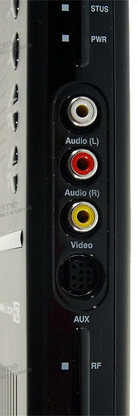
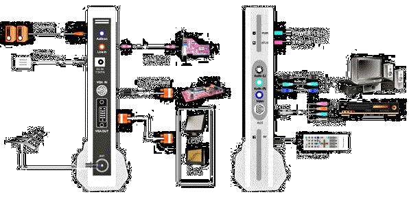 This solution allows to connect an Atari ST machine running in low-medium-high resolution to a LCD or CRT monitor using the Supera Color HD Box (referred as the SCHD box later in this text). Basically the SCHD box accept TV RF input, Composite Video input, S-Video input, YPbPr Input, or VGA input to produce a HD VGA output.
Important reminder: This solution can only be used on ST machines that are equiped with a RF modulator (like a STFM). If your Atari does not have an RF modulator look at this solution.
You first need to buy the Geniatech Supera Color HD Standalone External TV Tuner Box for LCD Monitors (1920*1200 Max Res). For example DealExtreme sell it for about $50. For the detailed specification about this box please follow the DealExtreme link.
 There are several possible solutions to connect an Atari with a RF modulator to this box and we will review them below. Most of the information presented here are extracted from the ST to VGA Success
 ![]() thread on the Atari-Forum.
thread on the Atari-Forum.
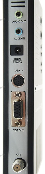
In all the following solutions the VGA output from the SCHD box needs to be connected to the VGA input of your LCD/CRT monitor and of course the box needs to be powered with the supplied power supply (7.5V). The proper input needs to be selected using the remote control or switches on the unit and the correct definition for your LCD/CRT monitor needs to be selected (up to 1920x1200 allowing to use HD monitors).
Connection using the Atari RF output
This is the easiest solution but also the one that gives the worst video quality. In this solution you just have to connect the Atari RF composite video output to the ANT antena input of the SCHD. This solution works for the Atari in Low and Medium resolutions.
Connection using the Atari Composite Video
The goal is to get the Atari Composite video signal coming from pin 2 of the Atari to one of the composite inputs from the SCHD. This solution works for low-medium resolutions.
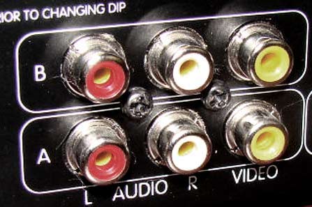
This can be done by using directly an Atari to RCA composite video cable. This cable is connected on one side to the DIN13 video output of the Atari and on the other side to the "Phono plug" (yellow RCA video plug) of the SCHD.
A second possibility is to use an Atari to SCART video cable. The SCART connector is then connected to a SCART to S-Video / Phono adapter. And finally from the adapter you have to connect either an s-video cable or a RCA-RCA cable to the corresponding input on the SCHD box.
Note that even if you use a s-video cable connected to the s-video input of the SCHD in fact you are not really using s-video signals (that the Atari does not produce anyway) but the composite video signal. The composite video signal from pin 2 of the Atari is connected to pin 20 of the SCART connecter, which is in turn connected to pin 3 (Luma Y) of the s-video connector. See Atari STFM Composite Video Signal section later for more technical details.
Connection using the Atari Monochrome Signal
It is also possible to take the monochrome output signal (from pin 11) from the Atari and to connect it the VGA input of the SCHD Box. This is done by using a DIN13 to VGA cable. This solution works only for the high resolution of the Atari.
Connection using the Composite and Monochrome Signals
It is useful to have a solution that works for all the resolutions of the Atari (low-medium-high). This require to use the composite video signal for the low-medium resolutions and the monochrome video signal for the high resolution. For that matter the best solution is to use an Atari monitor switch box. The input of the switching box is connected to the Atari, the monochrome output is connected to the VGA input of the SCHD and the color output is connected to the composite input of the SCHD. These connections are done using the previously described cables.
An example of connection of an Atari to a SCHD box has been given by Shredder11 in the thread here with nice pictures.
In term of cables a better solution would be to use a cable like this from techie_alison or an even better solution would be to build a similar cable where the SCART connector would be replaced by a RCA plug.
Cabling Summary
TODO
Back to the topConnection to an Atari without RF Modulator
In this case remember that the Atari does not produce a video composite signal. We have therefore two possible solutions:
- Generate a composite video signal that we can feed to a box described above, or
- Directly takes the outputs of the Atari and generate a VGA signal.
Generating a composite video signal
In this solution we use the RGB and sync signals to generate a composite video signal as well as a s-video signal. Note that this solution works even for an Atari without an RF modulator.
Two examples:
- The Amiga RGB to PAL/NTSC Adapter.
This solution is described by Anemos on the Amiga forum here uses the amiga converter adapted to Atari signals. - Using the Atari ST Evolution Video Adapter from Kjmann's Atari Sales.
Unfortunately this solution is not yet available. Look at project description. The project status as been moved to a new site (you first need to create an account to see the threads).
Generating directly a VGA signal
In this solution we use the RGB and Sync signals from the Atari to generate a VGA/SVGA signal that can be used directly by a LCD/CRT monitor. There are plenty of boxes on the Web that takes CGA/EGA RGB signals to produce VGA output but it seems that in many cases the box is not adapted to Atari signals or the results are not good.
For example the Ambery 15Khz RGB CGA YUV Component Video YCbCr to VGA Converter Scaler seems to be a nice solution on the paper but according to DarkLord it does not seems to work well: "works ok in ST Low (but not Med - blurry and text drops out)".
Gonbes GBS 8200/8220 CGA-EGA-YUV to VGA Converter
The Gonbes GBS 8200/8220 CGA-EGA-YUV to VGA Converter board that allows to connect an Atari ST machine running in low-medium resolution to a LCD or CRT monitor. The GBS-8200 and the GBS-8220 boards (referred as the GBS board later in this text) are almost identical the only difference beeing an extra VGA output on the 8220 model. Note that this model is sometimes known as GBS 6220.
Basically the GBS board accept CGA, EGA, YUV, and VGA inputs to produce a VGA output.
note: This solution is best suited for ST machines that are not equiped with a RF modulator. If your Atari have an RF modulator you can use the above solution otherwise you may need to recreate a composite synchro signal.
You first need to buy the Gonbes GBS 8200/8220 CGA-EGA-YUV to VGA Converter board. You should be able to find them from eBay for about $40. For the detail specification about this board read the user's manual.
As I was a bit confused about the different inputs connectors and the operating modes of the board so I first did some measurements and experiments. Here is a summary of what I have found.
There are two type of entries:
- one for YUV, and
- three for RGB
and three modes of operations (selected with the SW button):
- one for YPBPR,
- one for RGBS, and
- one for RGBHV
You also need to know that the matching RGB input pins of the different connectors (that is the 5-Pins connectors P3, the 8-Pins connector P10 , and the 15-Pins connector P11) are directly connected together. We have the following internal connections:
- Red Signal P3-1 P10-01 P11-1
- Green Signal P3-2 P10-02 P11-2
- Blue Signal P3-3 P10-03 P11-3
- Ground P3-4 P10-05 P11-7&8 (in fact P10 4 to 8 and 10 to 11)
- CSYNC/HSYNC P3-5 P10-13 P11-4&5
- VSYNC P10-14 P11-6
Therefore contrary to what the data-sheet says the P3, P10, and P11 connectors are equivalent (same input voltage and same frequency range) and using anyone of them will give exactly the same result. However note that connector P3 does not have a Vsync input.
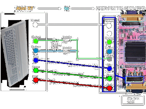
Setup procedure (I have been using the 5 pins P3 connector but you can use another)
- Connect the P13 (or P4) VGA output of the GBS-8220 Converter to your VGA monitor
- Connect the video signals from the Atari (DIN13) to the P3 (or equivalent) video input connector of the GBS-8220 converter:
- Red Video (Atari Pin 07) to GBS-8220 P3-1
- Green Video (Atari Pin 06) to GBS-8220 P3-2
- Blue Video (Atari Pin 10) to GBS-8220 P3-3
- CSync (Atari Pin 02) to GBS-8220 P3-5 using pass through resitor
- Ground (Atari Pin 13) to GBS-8220 P3-4
- Connect the GBS-8220 to a +5VDC Power supply. You can use the P9 2-pin connector or the P7 2-pin round connector. The power requirement for the GBS-8220 is +5VDC +/- .5VDC @ 2A. If the power supply cannot put out 2AMP then it may cause problems with the on-board CPU.
- First time you start the board the menu will be in Chinese. Press the Menu botton the board display a menu in Chinese use the up or down button to move the cursor in front of the entry 4. Press the Menu button the language menu is shown. Select entry 1 and validate with the Menu button you should now have the menus in English.
- You can now power the Atari. If nothing is displayed try pressing the AUTO (Down) button on the converter. This should self-adjust and lock-in the picture on your VGA output monitor. You also try to press the SW button to select another operating mode.
With the above connection using a 560 Ohm pass through resistor on C Sync I have been able to get a stable image using the RGBHV mode. I also need to enter the Display menu and adjust to 1024 * 768. Problem is that even playing on the RGB VR input I cannot get correct color. The white is pink! Overall quality of the image is not superb but acceptable.
I also made a second series of tests using the 15 pins P11 connector. Here I have been using HSync (Atari pin 9 to GBS pin 13) + VSync (Atari pin 12 to GBS pin 14) but unfortunately without success. I have tried with and without 560 Ohm resistors.
I have also tried with both of the above connections (CSync or HSync+VSync) to input Atari monochrome signal to the GBS board but without success (the image is frozen).
Back to the topCreating Composite Sync signal on an Atari STFM
 This may be useful if you have an Atari ST equipped with an RF modulator that produces a composite video signal on pin 2 (see video schematic).
One solution (proposed by Anemos) is to use an LM1881 signal separator, to convert the composite video input signal from the Atari to a composite sync signal. I do not know if any experiment has been done.
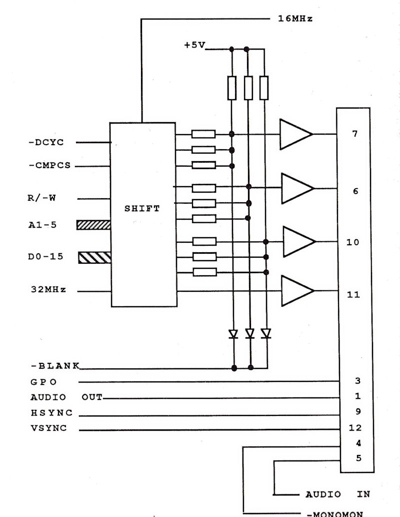
 Another solution still proposed by Anemos is depicted in the schematic on the right. A small video showing the Atari operating with this solution is available on YouTube. However this solution is criticize because the Hsync and Vsync signals are "shorten" together by the 1µF capacitor and this is obviously not good for the life of the glue (or MCU) chip.
Yet another solution from Simbo is to build an external board with circuitry similar to the one used in the ST without RF modulator. The original Atari schematic uses 2N3905 and 1N4004 that simbo replaces respectively by BC182 and 1N914. Complete project can be found here.
If you are using an Atari STE you can see on the schematic, presented above, that a composite signal CSYNC is produced on pin 6 of the LS04 U211. This signal is sent to pin2 of the MC1377. It seems that this signal is generated even if no RF modulator is installed. However the signal is not inteded to be used outside and therefore it is not amplified and it is not available on the video connector.
Back to the topCreating S-video Signals on an Atari STFM
Using s-video signals provides a better video quality than composite video signals but unfortunately the Atari does not generate these signals. However ppera has published on this page a description on how to modify an Atari ST, equipped with RF modulator, to produce s-video signals. The other alternative is to use an external box
Back to the topAtari STFM Composite Video Signal Description
The following section is taken directly from what 1024Mak has published on the Atari-Forum.
Here are some oscilloscope images showing the video outputs from an Atari STFM (with modulator). This is a UK model so operates to the PAL TV standard.
They show that the output on pin 2 of the Atari video connector is indeed composite video.
Also regarding the query about S-Video, well looking at these waveforms I don't think anyone is actually getting S-Video. What your equipment is probably doing is just using the information in the composite video feed (from pin 2) and ignoring the input from the "red / Chrominance" connection. Why do I say this, well the waveforms for the red "RGB" video output from the Atari do not show the type of signal needed to correctly operate the circuitry for a chrominance input.
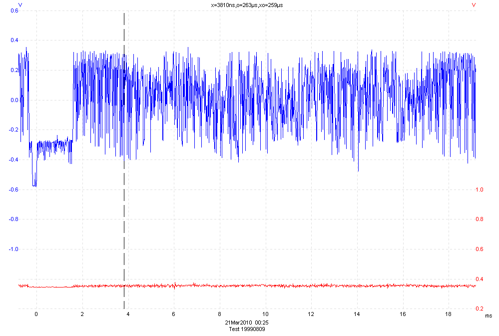
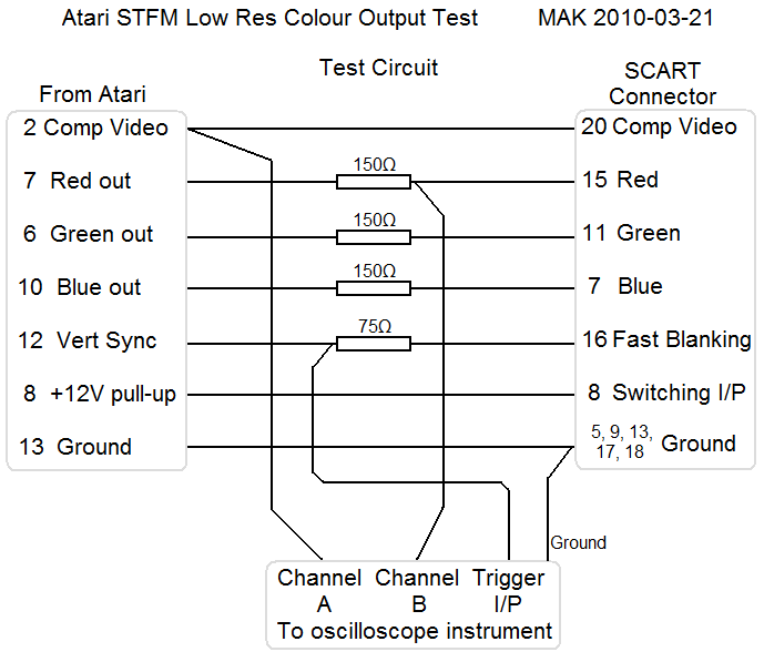
In all these images the blue trace is channel A of the oscilloscope which is connected to the Atari composite video (pin 2).
The red trace is channel B of the oscilloscope which is connected to the Atari red video output (pin 7).
For some of the traces I triggered the oscilloscope from the vertical sync output (pin 12).
Various images were used but I only provide those that show the important features most clearly. All were taken with the Atari set to low resolution video mode.
 On figure 1 you can see that in this image there is not much of the red trace. This is the red video output from the Atari, but the picture the Atari is showing has no red in it, so therefore there is no "red" picture information transmitted by the red video signal. The composite (blue trace) carries lots of picture information.
Figure 1 - A low resolution video frame with no red in the picture with a white border
 In figure 2 you can see that there is a lot of picture information in both the blue and red traces.
This is with a complex coloured picture being shown.
Figure 2 - A low res video frame with some red in the picture with a white border
 In figure 3 the red level (red trace) is fairly uniform for the middle section, but the composite (blue trace) varies much more as the different parts and colours of the image are displayed. You can clearly see the field sync pulses at the start of the trace.
Figure 3 - A low res video frame with a normal green desktop with a white border
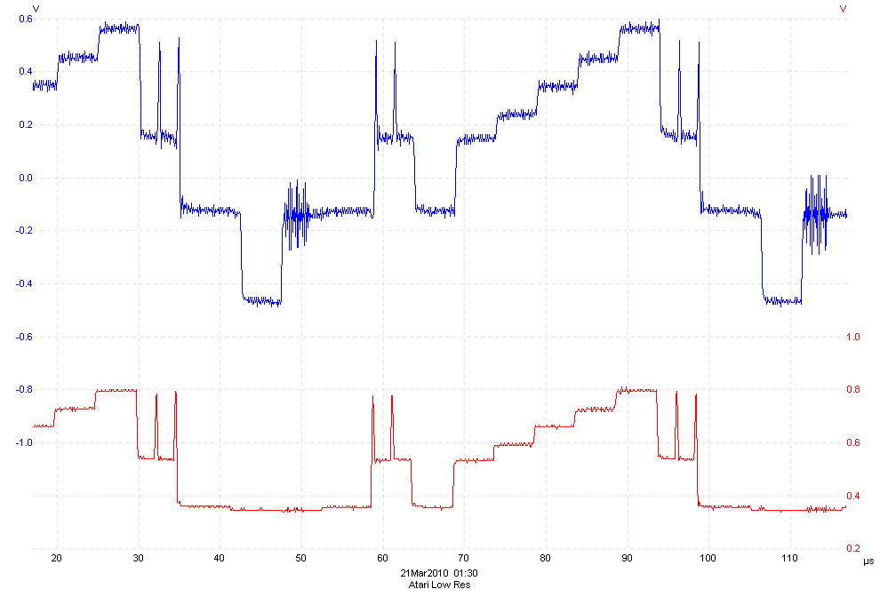 The set of traces in figure 4 shows one and a bit "TV" lines, the bottom parts of the blue trace are the sync pulses, then the first "spiky" bit is the colour burst signal, then you get the picture information (with some gray bars). The level then drops down to "ground" (0V) and then there is another sync pulse for the next line.
Figure 4 - Low res video lines with the Atari displaying a "test card" image
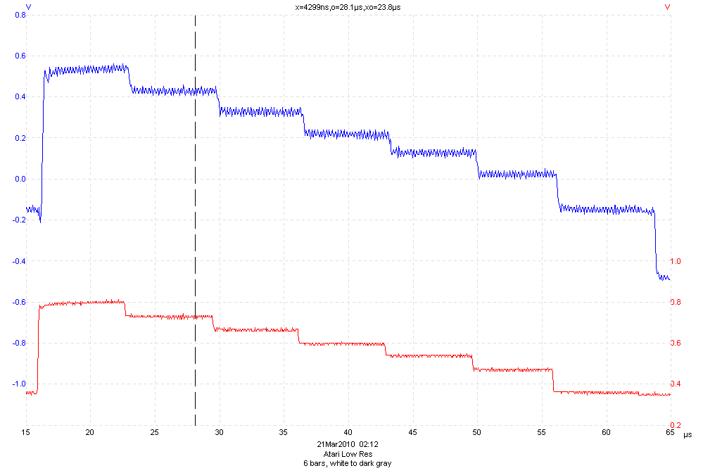 In figure 5 the Atari displays 6 vertical bars from white through various shades of gray to a very dark gray. The border is black. In this image (nearly one "TV" line) notice how similar the blue and red traces are. You can see a little bit of colour carrier information on the composite signal (blue trace) but not much as there is very little colour in the picture. Compare this to the image with six coloured vertical bars.
Figure 5 - A low res video line with the Atari displaying 6 bars, white to dark gray with a black border
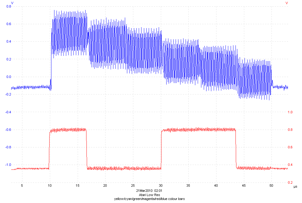 Figure 6 (nearly one "TV" line) clearly shows the type of signal you get for a composite colour signal (blue trace) when six coloured vertical bars are displayed. Note that above the ground (0V) level there are six steps corresponding to the six colours, each step is modulated with the colour carrier information. Compare this to the red video (red trace) which goes high only when there are red elements being displayed (for the yellow, magenta and red bars). Note that there is no modulated colour carrier information on this trace (but there is some noise and crosstalk from the composite colour signal).
Figure 6 - A low res video line with the Atari displaying 6 colour bars, yellow, cyan, green, magenta, red and blue with a black border
Figure 7 shows the test circuit used to record the oscilloscope images.
Basic Video Information
Here is some basic information on video. Video standards are ordered by decreasing Video quality: From best to worst.
RGB Video System
RGB the term referring to a type of component video signal used in the video. It consists of three analog signals—red, green, and blue—carried on three separate cables/pins. Extra cables are sometimes needed to carry synchronizing signals. This type of video is the best quality signal that can be carried on the standard SCART connector. Almost all computer monitors use RGB.
Back to the topComponent Video YUV
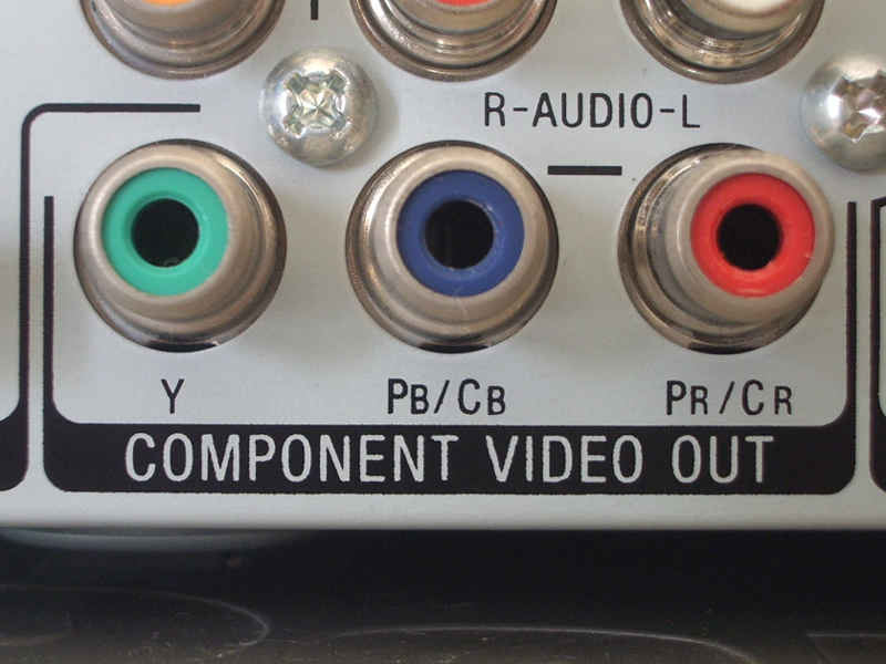 Component video is an analog video signal transmitted as three separate components video with sync on luma signals. Several variants exist but the most widely used is the YPbPr.
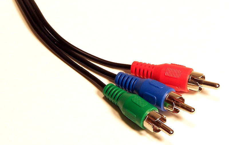
The component video signals are typically connected using RCA connectors Red (Pr), Green (Y) and Blue (Pb) or SCART connector.
S-Video
Separate Video, more commonly known as S-Video, also called Y/C is an analog video signal that carries video data as two separate signals: luma (luminance) and chroma (color). The color chrominance has to be encoded in NTSC, PAL, or SECAM. The luma signals also carry the Sync and blanking signals. Uses S-Video connector.
Back to the topComposite Video (CVBS)
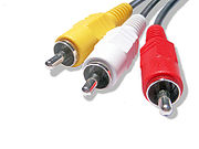
 Composite video is often designated by the CVBS acronym, meaning "Color, Video, Blank and Sync". It is usually in standard formats such as NTSC, PAL, and SECAM. It is a composite of three source signals called Y, U and V (together referred to as YUV) with sync pulses. Y represents the brightness or luminance of the picture and includes synchronizing pulses, so that by itself it could be displayed as a monochrome picture. U and V represent hue and saturation or chrominance; between them they carry the color information. The composite video signal is typically connected using an RCA jack (called a phono plug in the UK), normally yellow (with red and white for right and left audio channels respectively).
References
Datasheets
- MC1377 Datasheet
- AD725 Datasheet
- AD722 Datasheet (note that this chip is listed as obsolete)
- Application note Video-Standard Selection Circuit for the AD722 Using Low Cost Crystals
- MC13077 Datasheet
- TDA8501 Datasheet
- NTE879 Datasheet
- TEA2000 Datasheet
Information on video Circuits
- Atari RGB to Composite Video Converter
- Example circuit PAL Colour Encoder,
- Example circuit,
- VGA to PAL and NTSC converter,
- More info on video circuits and chips
Forums
- Atari Connectors and Cables
- S-Video mod for STE, ST ...
- ST to VGA Success
- Another failed ST -> vga experiement for me :)
- Atari ST to Composite, S-video, & VGA (color)
- GBS-8220 to Atari ST (2012)